Under 10ohm i only found 1 ohm resistors at home. With 1 ohm i hit 27.2v after 1 min. After 1 min tt does not climb higher. Is this OK or too high for the D3 ?
With two paralleled 15ohm (7.5ohm) i get about 25.3v.
Rather go 25.3V or 27.2v, which is acceptable ?
With two paralleled 15ohm (7.5ohm) i get about 25.3v.
Rather go 25.3V or 27.2v, which is acceptable ?
Last edited:
Ryan's recommendation:
The voltage input limitations are set by the amount of heat dissipated by CC1 and V1 . I usually aim between 26V and 27V, but I have used up to 28V with no issues as long as the temp on CC1 and V1 are not too far above around 55 Celsius.
I would not recommend going lower than 26V - as this was the voltage that I used in the simulation to get good performance, anything lower than 25.5V may affect performance.
2 x 1ohm in series gave me 26.4v, i will stay there. I used another PSU until now and i wonder how different this will sound 🙂
First i used the onboard resistor as i/v, but i made a tube based i/v now. What do i need to change to use this ? Only remove the I/V resistor or is there more to remove ? How do i bias it (with i/v resistor soldered or removed) ?
First i used the onboard resistor as i/v, but i made a tube based i/v now. What do i need to change to use this ? Only remove the I/V resistor or is there more to remove ? How do i bias it (with i/v resistor soldered or removed) ?
2 x 1ohm in series gave me 26.4v, i will stay there. I used another PSU until now and i wonder how different this will sound 🙂
First i used the onboard resistor as i/v, but i made a tube based i/v now. What do i need to change to use this ? Only remove the I/V resistor or is there more to remove ? How do i bias it (with i/v resistor soldered or removed) ?
Hi LinuxGeek,
Which tube circuit you using?
If using lampizators circuit- you need only to remove R33 and R32 as the negative current from the analogue outputs of the DAC will bias the tube to set the plate current.
Hi LinuxGeek,
Which tube circuit you using?
If using lampizators circuit- you need only to remove R33 and R32 as the negative current from the analogue outputs of the DAC will bias the tube to set the plate current.
Hi. Yes first i wanted to try srpp, just because i have all needed parts already available. So i remove r33 and r32. What about bias ? When using the resistor as i/v i played music and adjusted the output so i reached 0v. Will i need to do it a second time now or does the bias not change without r33 and r32 ?
Ty very much.
Having the grid at 0V will allow more current to go through the tube than if you have say -100mV on the grid with a 50R IV resistor. I think this will also change the linearity operating region of the tube. Also you may shorten the tubes life and wear out the cathode faster if you run too much current through your tube.
Anyone that knows tubes please correct me if im wrong.
So in short, no you wont be needing the CCS to get the output to 0V. I didnt use one when I tried this SRPP.
Anyone that knows tubes please correct me if im wrong.
So in short, no you wont be needing the CCS to get the output to 0V. I didnt use one when I tried this SRPP.
Hi. Yes first i wanted to try srpp, just because i have all needed parts already available. So i remove r33 and r32. What about bias ? When using the resistor as i/v i played music and adjusted the output so i reached 0v. Will i need to do it a second time now or does the bias not change without r33 and r32 ?
Ty very much.
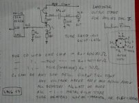
Here are the curves for the 6N1P that is in the Lampizator circuit. For a given plate voltage it shows that as Vg increases (from 0 to negative Vg), the plate current decreases. Plate current is maximum when Vg=0 as Ryan stated.
In the Lampizator circuit, it shows a 680 Ohm cathode bias resistor that provides -1V of bias. The -2mA offset of the TDA1541A provides additional grid bias voltage across resistor Ra (60 to 80 Ohm specified). So the offset current would provide an additional -0.12V to -0.16V of bias voltage.
If the TDA1541A offset current is nulled, then there is no additional bias voltage, which would then change the tube operating point. However since the cathode bias resistor provides a substantial portion of the bias voltage, the loss of the bias voltage from the current offset would not destroy the tube.
Interesting note - the SRPP circuit is push-pull:
The Tube CAD Journal,SRPP Decoded
Attachments
Hi Ryan
I received the second D3 and etc this past week.
I had thought I would already have the first board cased up and running in my system, but this project has gone very slow due to house renovations.
I can’t have electronics lying around in the living room without a case.
I have finished my case and am installing the power supplies.
Since I already have the second D3 and CapMx, and I have already made accommodations in the case for them and the v2 I2StoSIM board I was considering just installing it all now.
I was hoping you or someone else who might have put together a dual/mono D3 might be able to go over the details of how the output wiring should be done. A picture would be ideal.
I will only be using iv resistors right now with the hopes that my system will have enough gain.
You had mentioned wiring the output in differential mode was desirable especially if needing iv transformers?
It’s something that I’ve tried reading up on but I don’t understand.
Hi Kevin,
Glad you received the PCBs ok.
If using two D3 boards in a dual mono config I would recommend using one D3 board for the left channel and one for the right, you'll get better channel separation this way and it should sound better.
If you want to go balanced use one D3 board for the left and inverted left, and the other D3 board for right and inverted right. You will need to use a balanced output stage for this. For most it will be easiest to use a transformer with a CT on the primary which will be connected to GND, and each end of the primary connected to left and inverted left / right and inverted right for the other transformer. On the secondary side- connect one side to GND and the other is the signal output. You must also put a load resistor across the secondary which will determine the gain. I'm using 1+1:37+37 transformer with a load resistor of 10k. The load resistor doesn't need to be of high quality as the IV conversion is done by the transformer.
The main benefit of running balanced is the cancelation (partial) of 2nd harmonic distortion. And you can hear the difference, im very happy with how my setup is sounding.
Sorry no picture as I think the mess my DAC is in will only confuse. 🙂
Hi Ryan
I was hoping you or someone else who might have put together a dual/mono D3 might be able to go over the details of how the output wiring should be done. A picture would be ideal.
I will only be using iv resistors right now with the hopes that my system will have enough gain.
You had mentioned wiring the output in differential mode was desirable especially if needing iv transformers?
It’s something that I’ve tried reading up on but I don’t understand.
Hi Ryan
Thanks for the response.
Since I don’t already have specific transformers for this DAC application and I wanted to try iv resistors alone to see if I have enough gain the first option of dual mono makes sense.
When connecting my rca chassis output wiring to each D3 board for either the right or left channel, what orientation should it be in regarding the two sets of output pads for each board? I have one pair of +/-wires for each rca output socket versus two pair +/- output pads on each D3 board.
I have another question that crossed my mind while trying to search and understand more on the subject of dual mono implementation of the tda1541.
Will using two D3 boards in a dual mono configuration increase the current output for each channel and allow me to use lower value iv resistors to decrease distortion?
Will using two D3 boards in a dual mono configuration increase the current output for each channel and allow me to use lower value iv resistors to decrease distortion?
Hey guys,
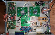
Got the new correct resistors in place and am testing. All output groups on the V2 Sim board seem to work driving D3 boards. This is my current test setup which must be a summed version. It works and makes decent sound.
I've built a few more D3 boards and will eventually try a quad version.
Anybody care to post the various wiring schema or know where to find illustrations. How to out of the V2 Sim to D3's and out of the D3's into output stages.
This thread could probably really use this info in it.
Mark K.
Attachments
Last edited:
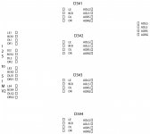
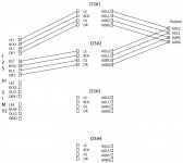
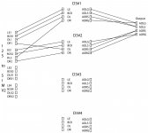
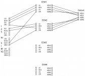
Here is a possible wiring scheme template and my current configuration.
Feel free to post schemes or possible combinations and titles. Not sure what mine is exactly other than summed output.
Mark K.
Feel free to post schemes or possible combinations and titles. Not sure what mine is exactly other than summed output.
Mark K.
Attachments
Hi Kevin,
Glad you received the PCBs ok.
If using two D3 boards in a dual mono config I would recommend using one D3 board for the left channel and one for the right, you'll get better channel separation this way and it should sound better.
If you want to go balanced use one D3 board for the left and inverted left, and the other D3 board for right and inverted right. You will need to use a balanced output stage for this. For most it will be easiest to use a transformer with a CT on the primary which will be connected to GND, and each end of the primary connected to left and inverted left / right and inverted right for the other transformer. On the secondary side- connect one side to GND and the other is the signal output. You must also put a load resistor across the secondary which will determine the gain. I'm using 1+1:37+37 transformer with a load resistor of 10k. The load resistor doesn't need to be of high quality as the IV conversion is done by the transformer.
The main benefit of running balanced is the cancelation (partial) of 2nd harmonic distortion. And you can hear the difference, im very happy with how my setup is sounding.
Sorry no picture as I think the mess my DAC is in will only confuse. 🙂
Attached "Dual Mono" or not?
Attachments
Hi Mark
Thanks for the update on your DAC project and the information and illustrations relating to the output wiring. I think they will be useful.
It’s good to know you have it working with two boards parallel on the outputs like that. I wonder if you’re getting the benefit of better channel separation that was mentioned regarding dual/mono operation? It seems like you would get the additional current, but I’m not knowledgeable in the matter.
The issue of how the I2StoSim board connected to the D3 only faintly occurred to me. I figured I just needed to make sure the connections weren’t mixed up.
Hopefully we’ll get some feedback on this subject.
The only thing I found regarding wiring multiple D3 boards was Ryan’s post several pages back of his quad stack of D3 boards he was working on to test with output transformers. I can only see that on the top board he grabs one ground and both signal outputs.
I’m finishing up my power supply connections and a few other things...whenever I’m not working on the sunroom renovation...hopefully my D3 will finally be up and running sometime soon.
Thanks Chrome,
I haven't attempted other connections yet but I am enjoying the builds and sound produced so far!
I hope the wiring can be clarified and understood. I think it's important to get the schemes illustrated here for end users not wanting to damage stuff. I've put a fair amount of time and money towards this and would hate to end up with unusable parts.
Thanks,
Mark K.
- Home
- Group Buys
- DIY TDA1541A PCB "D3"