
Are the Jtest measurements loopback? With a common clock some of the jitter will be suppressed. This will help interpret the jitter: https://www.bramjacobse.nl/wordpres...21/04/TN-118_Measuring_Jitter_with_J-Test.pdf The spectra don't show the 250 Hz stuff. Maybe a digital loopback will show better what a jitter free display would look like. Usually on the 16 bit stuff there is a pattern at 250 Hz intervals:

This proved to be a wise suggestion. Thank you Demian 🙂Maybe a digital loopback will show better what a jitter free display would look like.
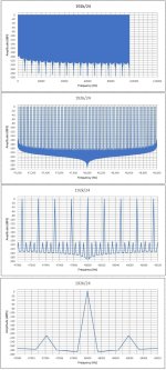
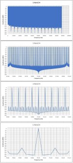
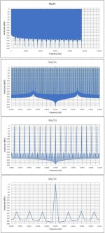
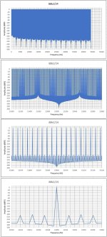
From REW I recorded on file the J-test signal (120sec) on 6 sampling rates.
From Audacity I exported the FFT of its file (65536 points, Rectangular window) in .txt files.
With Excel I made the diagrams of the FFTs (attached)
The .wav files can be downloaded from Dropbox. there will bethere for 10 days
https://www.dropbox.com/scl/fi/gdld...ey=8cixv3hwhylmll8ttmm9f3ifn&st=i4w0qf2e&dl=0
https://www.dropbox.com/scl/fi/x4kb...ey=z6ws56z07kqreropjgvezbomk&st=hnfnd2r3&dl=0
https://www.dropbox.com/scl/fi/yajl...ey=z3zbbl4qcpo5qd1rommh5hzrt&st=4vrm4279&dl=0
https://www.dropbox.com/scl/fi/p9ja...ey=gln8wwb63ejbzbypdrzo1f4l3&st=mb8ysqnf&dl=0
https://www.dropbox.com/scl/fi/q6zt...ey=nyvbaio8qnknr532vvm625oyx&st=h34zbz7z&dl=0
https://www.dropbox.com/scl/fi/vzrd...ey=ltb0p4syvpjf4ya6by4lhqw7m&st=d86bkz7y&dl=0
George
Attachments
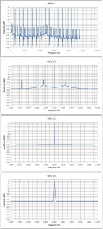
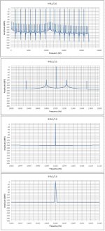
Yes. Those were loopback (same card's DAC and ADC).Are the Jtest measurements loopback? With a common clock some of the jitter will be suppressed.
Here I use two sound cards
First attachment is EMU 0404 as the DAC and Kostas V2 as the ADC
Second attachment is Kostas V2 as the DAC and EMU 0404 as the AVC
44k1/16
Attachments
XLR I/O Gerber Files. Double checked but not built.
Pin #1/sleeve to chassis. Builders decide where the chassis is attached. Also, added output diode clamps for basic protection. Finally, there was a weird crosstalk problem around the "dual channel" switch, spotted by George. Surprisingly, 0,7 mm clearance is not enough for line level audio. So, I modified the pads to allow for 1,2 mm clearance. Hopefully, it will be sufficient.

Released for enthusiast diyers. Should anyone build it, please report back.
Pin #1/sleeve to chassis. Builders decide where the chassis is attached. Also, added output diode clamps for basic protection. Finally, there was a weird crosstalk problem around the "dual channel" switch, spotted by George. Surprisingly, 0,7 mm clearance is not enough for line level audio. So, I modified the pads to allow for 1,2 mm clearance. Hopefully, it will be sufficient.
Released for enthusiast diyers. Should anyone build it, please report back.
Attachments
Hi George,I expect knowledgeable members to chime in, rate and comment on those numbers and figures.
🙂
George
I see some evidence at ASR from some years ago that they sometimes looked at jitter noise skirts. There is an example included in a post from Amir at: https://www.audiosciencereview.com/...ro-portable-dac-amp-review.46550/post-1661890
In order to make sure this doesn't accidently go off topic because of me, may I ask if you are you interested in random noise jitter too, or only interested in deterministic jitter?
Mark
Hi George,
I think measuring random noise jitter could in principle be performed as you stipulate. However, it would probably be less standardized than J-Test for deterministic jitter, harder to do and to interpret results as compared to deterministic jitter, and maybe more costly for a good test setup.
Should be no surprise on most or all the above. Otherwise it would likely already be a common measurement.
IOW, I would expect its not necessarily inaudible in all cases. More likely its rarely done because its too much trouble for a little diy fun.
Mark
Could anybody give any guidance about how the noise level/THD of an ADC is influenced by clock jitter? In a soundcard DAC/ADC loopback measurement running on a common clock, the clock jitter is cancelled, isn't it?
At least for modern data converters, jitter is probably not perfectly canceled, but its not exactly uncorrelated either. IOW, there may tend to be some cancelation effect.
Otherwise the process would seem to violate causality. A DAC has an output filter and an ADC has as input filter. It takes some time for a signal to pass through both filters. Thus for a given sample point the D/A conversion probably cannot be on the exact same MCLK clock pulse as the A/D conversion.
Otherwise the process would seem to violate causality. A DAC has an output filter and an ADC has as input filter. It takes some time for a signal to pass through both filters. Thus for a given sample point the D/A conversion probably cannot be on the exact same MCLK clock pulse as the A/D conversion.
Last edited:
Not phase. Phase is a property of the frequency domain. In the time domain there is only time and time delay.
Say, you have an MCLK frequency of approximately 22MHz and you have a 256x oversampling dac. Further suppose you are going to convert one sample from a wav file. Let's number the clock pulses out of the MCLK oscillator module. At the first MCLK pulse, P(1) the dac starts converting the sample. At P(256) the sample from the wav file has finished being converted from digital to analog. From there it passes through the dac analog output reconstruction filter with some time delay which takes longer than the period of one MCLK pulse. So, say, it passes out of the dac as an analog signal at MCLK pulse, P(270). From there it passes through the ADC anti-alias filter by time P(275) and starts oversampled conversion from A to D. Say it finishes oversampled D to A conversion by MCLK pulse (570). Obviously the A/D conversion has taken place at a later time than the D/A started converting the wav file sample to analog. Right?
So how would MCLK jitter cancel out? The jitter on MCLK pulse P(1) is not the same jitter error as on MCLK pulse P(570).
For the jitter to exactly cancel out, the ADC would have to use the exact same MCLK pulses as the DAC did. But as we just saw, they didn't use the exact same MCLK pulses.
Now, part of what clocks do is wander around a little in frequency. Let's say that wandering around is a timing error we will call E1 (a timing error is what jitter is!). Let's also say there is a smaller more random error component to clock timing we will call E2. So the total timing error will be E1 + E2 for any given MCLK pulse: P(k) timing error is from E1(k) + E2(k).
Since E1 is likely bigger than E2, and E1 is changing more slowly than E2, the timing error at the DAC and at the ADC may be mostly a function of E1 (the clock frequency wandering around slowly, such as at a drift rate equivalent to low audio frequencies). In that case the DAC timing error may mostly about the same as the ADC timing error, so E1 mostly results in jitter than cancels.
OTOH, E2 is more random and changes more rapidly, so E2 may be very different for the conversion pulses while the DAC was converting the wav file sample to analog as opposed to what E2 was doing later while the ADC was converting the analog signal back to digital.
In this E1 and E2 model, and its just a model I made up to illustrate a point, there will be a lot of jitter correlation between the DAC and the ADC due to E1, but they will not cancel exactly due to E2.
Does that more or less long-winded explanation make some intuitive sense?
Last edited:
It does 🙂
How many ns of delay you think will do the trick?
I have some meters of RG58 and some BNC connectors to spare for building a coaxial delay line btn DAC out and ADC in.
http://www.ve2azx.net/technical/CoaxialCableDelay.pdf
Crossover frequency will be around 100kHz (will be checked) and this may cause some delay inconsistency at audio frequencies.
We'll see
George
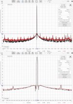
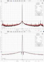
I'm posting this without being sure it's relevant to the discussion. From REW manual :
"If the Monitor clock match option is selected REW will check for differences between the replay and record clock rates when using a multitone test signal or an FFT-locked sine signal and warn if the clock rates do not match and a rectangular window should not be used. If the window is not rectangular and the clock rates do match it will suggest using a rectangular window for greatest accuracy in the results."
I do get the message to use a rectangular window. I don't know if it has anything to do with this "Clock Δ: 0.0 ppm" figure.
MarkYou want to decorrelate the DAC and ADC?
As far as I understand, In your post #210 you make the hypothesis that the small time delay caused by the DAC-out filter and the ADC-input filter is the cause of only a non-perfect cancellation of jitter when DAC and ADC are on the same soundcard.
Following that hypothesis, I thought that increasing the time delay btn soundcard's DAC-out and ADC-in, would make the jitter cancellation effect even weaker.
I don't think that any delay can decorrelate DAC from ADC, as clock rate remains the same
Kostasthis "Clock Δ: 0.0 ppm" figure.
This "Clock Δ" has to do with clock rate difference btn DAC and ADC
George
.
George,
The sort-of explanatory models I suggested were really to help develop some intuition, but probably they are pretty simplified.
Regarding correlation of jitter errors over time and jitter cancelation, my feeling is that cancelation is probably largely a function of correlation. So, reducing jitter cancelation would probably involve some partial decorrelation of timing errors as a function of time. Maybe that's too abstract to be of much use though.
With regard to your idea of extending D/A output to A/D input time-delay, seems like it might help. However, my guess would be that it would depend a lot on the particular clock. If it were a very, very good one with very low phase noise and oven-ized for frequency stability over time, then its jitter is very low to begin with and is probably not going to change much over time.
Thus, it seems like the analog delay idea might have more anti-cancelation effect with a lower quality, more jittery clock, and perhaps one which tends to drift around in frequency more over time.
Also, I suppose it would be possible to measure time delay from DAC output to ADC input with an oscilloscope. Using a pulsed audio signal at 10Hz or 100Hz repetition rate might make it possible to look for pulse edges at DAC output and ADC input in order to get some idea of filter delays.
Don't know if any of the above thoughts will be helpful or not.
Mark
"I suppose it would be possible to measure time delay from DAC output to ADC input with an oscilloscope"
Perhaps it is more practical (for me it is more conceivable) to measure the delay in the digital domain. I mean we can precisely measure the delay between the digital input signal (I2S or whatever) of the DAC and the digital output signal of the ADC with the same format, clock rate, bit depth. The link between them in the analog domain is just a piece of loopback cable without any measurable propagation delay, anyway.
Perhaps it is more practical (for me it is more conceivable) to measure the delay in the digital domain. I mean we can precisely measure the delay between the digital input signal (I2S or whatever) of the DAC and the digital output signal of the ADC with the same format, clock rate, bit depth. The link between them in the analog domain is just a piece of loopback cable without any measurable propagation delay, anyway.
Analog filters may have more delay than a loopback cable itself. Depends on the particular filter design. However, there is nothing wrong with measuring overall delay in the digital domain.
The question is more like, how much does knowing a number for a given delay help to know how much jitter cancellation is taking place?
The question is more like, how much does knowing a number for a given delay help to know how much jitter cancellation is taking place?
You run too fast.The question is more like, how much does knowing a number for a given delay help to know how much jitter cancellation is taking place?
The 'delay/jitter cancellation' relationship is still a mere hypothesis.
🙂
George
- Home
- Design & Build
- Equipment & Tools
- DIY soundcard intended for measuring amplifiers