I understand. There are two criteria that do not meet easily. The circuit ground should not touch mains earth, while it should connect to the potentiometers' shafts. The first soundcard was put in a chassis with the power supply built in so it had to be connected to mains PE. The potentiometers were then connected to circuit ground and insulated from the chassis with nylon washers. This soundcard is designed to use external psu so it doesn't need mains PE. That makes it very handy to connect the front panel - and the whole chassis- to circuit ground and be done with it. In this case pin #1 is both chassis and circuit ground. If you are going for a custom chassis you should improvise so that these requirements are fulfilled. The question is where commercial XLR to RCA or TS adapters -if they exist- connect ground coming from the SE end, to pin #1 or #3?
For a test/measurement system as this, I'd suggest to the SE output to the soundcard as follows:The question is where commercial XLR to RCA or TS adapters -if they exist- connect ground coming from the SE end, to pin #1 or #3?
output RCA tip --> balanced input "hot"
output RCA ring --> balanced input "cold"
At least that's how I do it with my RTX6001, which has the XLR pin 1 attached to the chassis, which in turn is on PE/mains-earth.
So, switch returns as bal/unbal and connects pin #3/ring either to cold or ground. Pin #1/sleeve currently stays not connected to anything. I see the standard XLR to RCA/TS adapters to short circuit pin #3 and #1. And then, there is the neutric ring pin "G" also not connected. Depended on chassis/front panel configuration as explained in post #181, you could bridge pin #1 and G with a short wire marked on the bottom side. What do you think?
I think you should not worry about an SE input. Just stick to the diff input.
I also think that since you are designing a piece of test equipment, it should not be "blessed" with the pin-1 problem. Just connect pin-1 as it should be and then leave it alone.
Edit: this is a nice and short description of how pin-1 must be used and connected.
I also think that since you are designing a piece of test equipment, it should not be "blessed" with the pin-1 problem. Just connect pin-1 as it should be and then leave it alone.
Edit: this is a nice and short description of how pin-1 must be used and connected.
Last edited:

That assumes pin-1 and the housing of the XLR socket is always connected inside the plug or the cable. Is it?Pin #1/sleeve permanently attached to chassis via XLR socket ring.
I'd simply follow the standard procedure of connecting pin-1 to the chassis.
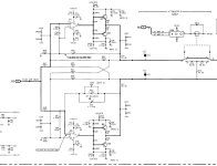
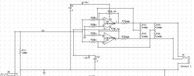
The output driver addresses a lot of connecton issues. I believe it is decended from the output driver of the HP 8903 with a self balancing circuit that adapts to a balanced drive, or short the - to ground and the output voltage adjusts to stay constant. It can also deal with ground loops if the low side is not grounded. The circuit actively senses the voltage differential at the load.
On almost every XLR cable I have seen (lots) pin 1 ties to the shield and the connector shell. Similar with TRS cables. A TS (mono) cable with short the low side to ground through the sleeve.
On almost every XLR cable I have seen (lots) pin 1 ties to the shield and the connector shell. Similar with TRS cables. A TS (mono) cable with short the low side to ground through the sleeve.
I didn't know about HP 8903. Here balanced output is straightforward from the DAC. The driver can do conversions but it's not asked to. Although it can stand outputs shorted to ground, for SE I prefer to move XLR pin #3 to ground leaving the driver's negative phase disconnected. It will deliver the same THD+N context but it can't keep constant levels. Ground loops are addressed by the ADC input and the isolated psu.
Yes! And if not, the soundcard's output XLR pin #1 connected to shell/chassis. That would work with anything.
On almost every XLR cable I have seen (lots) pin 1 ties to the shield and the connector shell. Similar with TRS cables. A TS (mono) cable with short the low side to ground through the sleeve.
Yes! And if not, the soundcard's output XLR pin #1 connected to shell/chassis. That would work with anything.
It's true the output is unprotected unlike signal and power supply inputs. There was not any protection in the first version either where THAT drivers were used. Not even common mode DC offset compensation. I think DC offset and RFI are not an issue since interconnects should be kept short for this job anyway. I understand that the diodes alone are good for a surge of an accidental 48V phantom power connection. Adding current limiters for more robustness defeats the purpose of this soundcard. That said, it's easy to add BAV199 diodes, but it should be made clear that it's not a forgiving protection.
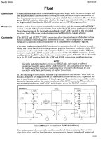
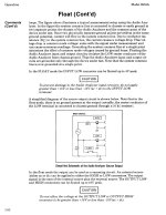
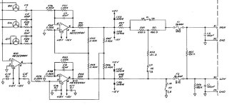
The output circuit schematic is in service V2 for the HP 8903. I clipped it and attached it below. Also a variant I made for the QA400 output. And the output for the first gen Boonton 1120. (Boonton made it to steal some business from HP in a complex military instrument setup. Its still in production.) What is neat is that if its set to drive 1V it doesn't matter if the load is floating/balanced or single ended with the - out shorted to ground. it will still be 1 volt. I find that to be very useful. The later Boontons made the whole output circuit + oscillator float. AP uses an output transformer to isolate the output but AP can still get you confused on what the output voltage is between balanced and unbalanced.
Attachments
This is what makes engineers stand above humble diyers... I was happy to get away without ground loop noise but the only constant in my soundcard is the requirement for manual adjustments all the time. 🙂
I'm visualizing a complete SMT work when I close my eyes. Not a chance with eyes wide open...
I'm visualizing a complete SMT work when I close my eyes. Not a chance with eyes wide open...
Never say never...I'm visualizing a complete SMD work when I close my eyes. Not a chance with eyes wide open...
I have a development project for your next winter


George
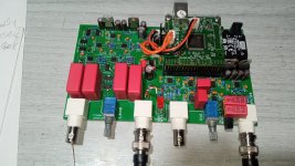
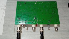
I have the Version 2 soundcard here and yesterday i did some tests.
First checking for noise.
I fed 4.85Vdc from a basic linear PSU with an LM323K regulator.
Bare-bones the card catches some 50Hz mains radiation, not much, it shows at around -80dBFS.
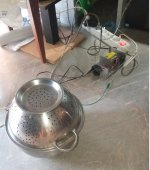
I don't have a proper metal box for it now, instead I used cooking-ware for shielding it.
First checking for noise.
I fed 4.85Vdc from a basic linear PSU with an LM323K regulator.
Bare-bones the card catches some 50Hz mains radiation, not much, it shows at around -80dBFS.
I don't have a proper metal box for it now, instead I used cooking-ware for shielding it.
Attachments
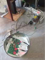
diy shielding worked great.
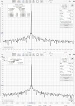
The card is dead silent at low frequencies. The psu arrangement of Kostas does a great job.
There are some glitches higher up, at different frequencies with different sampling rates. They peak around -155dBFS.
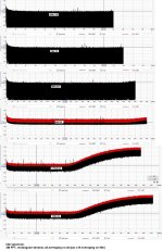
SE Loopback test, Rout to R in
Red is peak values (no averaging, black is final values after averaging)
The card is dead silent at low frequencies. The psu arrangement of Kostas does a great job.
There are some glitches higher up, at different frequencies with different sampling rates. They peak around -155dBFS.
SE Loopback test, Rout to R in
Red is peak values (no averaging, black is final values after averaging)
Attachments
Last edited:
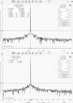
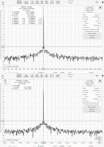
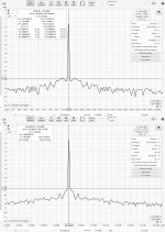
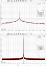
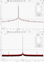
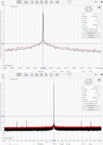
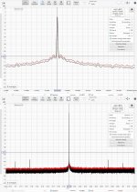
I was curious to see how "jittery" the card is.
I followed the old approach to compare FFTs (*) of sinusoidal signals at 1kHz and at Fs/4.
If close freq FFT skirts at FS Fs/4 (and noise floor level) are not much higher that those at 1kHz, it is said that jitter level is not worrisome.
Averaging is x8 on all.
(*) close in phase noise is the frequency domain equivalent of time domain jitter
Attachments

Last edited:
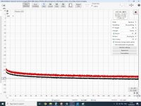
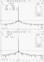
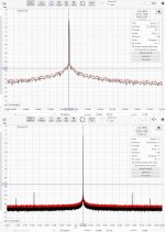
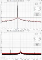
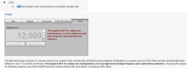
Then, I noticed REW software provides J-test. I did that too (x8 averaging).
Attachments
- Home
- Design & Build
- Equipment & Tools
- DIY soundcard intended for measuring amplifiers