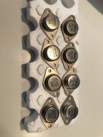
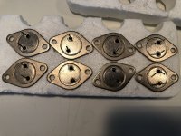
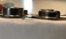
Hi guys, Is the casings on Sony SK60/SJ18 and Yamaha SK76/SJ26, suppose to differ in size between N and P part?
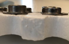
I just noticed the "SK" parts are a bit taller than the "SJ" parts I've got, and think this is a bit strange, especially since my (most likely) genuine SK82/SJ28 looks like they're equal.
I just noticed the "SK" parts are a bit taller than the "SJ" parts I've got, and think this is a bit strange, especially since my (most likely) genuine SK82/SJ28 looks like they're equal.
These devices are in the TO3 metal can package, which should be of the same dimensions despite who manufactured them, this is an industry standard outline.
The TO3 registered outline also specifies the package height. For a standard TO3 outine the diamond shaped base is 40.13mm long by 27.17mm wide with the mounting holes on 30.15mm centres. The height of the cap measured from the bottom of the base is 11.43mm.
Hoping to get help with a couple questions:
1. I read earlier posts with Bones and ZM noting that with the silicone pads provided with the kit, thermal grease is not needed. Just confirming that this is indeed the case. I have already built one VFET amp with Keratherm pads and have been using it for months without thermal grease, no issues so far.
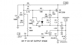
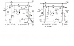
2. When using the OS2 boards with a 2SJ28 VFET (instead of 2SJ18), R1 should be 1.5 ohms and R2 should be shorted, correct?

1. I read earlier posts with Bones and ZM noting that with the silicone pads provided with the kit, thermal grease is not needed. Just confirming that this is indeed the case. I have already built one VFET amp with Keratherm pads and have been using it for months without thermal grease, no issues so far.
2. When using the OS2 boards with a 2SJ28 VFET (instead of 2SJ18), R1 should be 1.5 ohms and R2 should be shorted, correct?
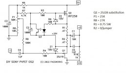
With the 2SJ28 you can take advantage of its higher power dissipation and run it at 1.6A as the part 1 circuit. R2 would be shorted and R1 would be 0.75R. With 1,6A, resistor power dissipation would be 1.6A x 1.6A x 0.75R = 1.92W. So single 5W 0.75R or parallel 2W 1.5R.
Attachments
Hi.Hi guys, Is the casings on Sony SK60/SJ18 and Yamaha SK76/SJ26, suppose to differ in size between N and P part?
I just noticed the "SK" parts are a bit taller than the "SJ" parts I've got, and think this is a bit strange, especially since my (most likely) genuine SK82/SJ28 looks like they're equal.
I have checked mine (a sample of 8) and the Sony sk60 and sj18 are the same height. Don't know about the Yamaha parts.
It may help if you post some pictures of your VFETS.
Regards.
Thanks Gary s and jotom750, guess they could be fake parts. Will try to post some pictures when I get home.
So slightly different version of the same question. If I was actually using a 2SJ18 but my speakers are a nominal 10 ohm load any potential benefit to using something like 0.66/0.33R or 0.75/0.25R since the load is closer to the 16 ohm load that the 2SJ18 would prefer to see?With the 2SJ28 you can take advantage of its higher power dissipation and run it at 1.6A as the part 1 circuit. R2 would be shorted and R1 would be 0.75R. With 1,6A, resistor power dissipation would be 1.6A x 1.6A x 0.75R = 1.92W. So single 5W 0.75R or parallel 2W 1.5R.
ETA also using OS2 output boards
I’m confused, Ben. You are recommending a different value for the CCS resistor than the p1 schematic. Is that correct?With the 2SJ28 you can take advantage of its higher power dissipation and run it at 1.6A as the part 1 circuit. R2 would be shorted and R1 would be 0.75R. With 1,6A, resistor power dissipation would be 1.6A x 1.6A x 0.75R = 1.92W. So single 5W 0.75R or parallel 2W 1.5R.
Edit: completely failed to see R2 on the p1 schematic. Yes, 0.75R. That makes sense. All good, thank you!
Last edited:
It may help if you post some pictures of your VFETS.
Regards.
Attachments
If I remember correctly, I have a few 2SJ18 of differing height as well ... so in my opinion, that isn't conclusive as to original or fake.
How are they measuring in terms of resistance across D-S, D-G, and G-S ?
Regards, Claas
How are they measuring in terms of resistance across D-S, D-G, and G-S ?
Regards, Claas
OS2 2SJ18 was optimized for 8 Ohm load. Your 10 Ohm is much closer to 8 Ohm than 16 Ohm so I suggest you keep the resistors as designed.So slightly different version of the same question. If I was actually using a 2SJ18 but my speakers are a nominal 10 ohm load any potential benefit to using something like 0.66/0.33R or 0.75/0.25R since the load is closer to the 16 ohm load that the 2SJ18 would prefer to see?
ETA also using OS2 output boards
However I'm no expert. My suggestion is based on what I read in NP's OS2 writeup. 🙂

Well, to be honest I don't know how they should measure, but here is roughly what I got:If I remember correctly, I have a few 2SJ18 of differing height as well ... so in my opinion, that isn't conclusive as to original or fake.
How are they measuring in terms of resistance across D-S, D-G, and G-S ?
Regards, Claas
J26 D-S:1.3ohm G-D/S: 8.3Mohm.
K76 D-S:1.8ohm G-D/S: 11Mohm.
J18 D-S:1.3ohm G-D/S:4.4Mohm.
K60 D-S:2.1ohm G-D/S:11.7Mohm.
Both devices of every model measure about the same.
Hoping to get help with a couple questions:
1. I read earlier posts with Bones and ZM noting that with the silicone pads provided with the kit, thermal grease is not needed. Just confirming that this is indeed the case. I have already built one VFET amp with Keratherm pads and have been using it for months without thermal grease, no issues so far.
2. When using the OS2 boards with a 2SJ28 VFET (instead of 2SJ18), R1 should be 1.5 ohms and R2 should be shorted, correct?
View attachment 1062419
Hi,
I have a pair of the 2SJ28 VFET and my R1 & R2 values are 0.47 ohms.
Are you guys saying that I could replace R1 with a single 0.75R
Or am I miss-interpreting something here?
Yes, if you are using OS2 boards with 2sj28, then R1 on the OS2 board should be 0.75R and R2 should be a short. Study the two circuits above and you’ll see it. Also read all three articles.
If you have a working amp and it sounds good, don’t worry about it and just enjoy.
If you have a working amp and it sounds good, don’t worry about it and just enjoy.
Not yet finished waiting on my power switch to show up, I just skipped the output relay and find the turn on thump pretty minimal my aleph j with semi-souths is definitely a little worse. Used 2 x PO89ZB one for each channel.
Hi Golyd:Well, to be honest I don't know how they should measure, but here is roughly what I got:
J26 D-S:1.3ohm G-D/S: 8.3Mohm.
K76 D-S:1.8ohm G-D/S: 11Mohm.
J18 D-S:1.3ohm G-D/S:4.4Mohm.
K60 D-S:2.1ohm G-D/S:11.7Mohm.
Both devices of every model measure about the same.
Those measurements are all what you would expect from real VFETs, and from working ones in that case. I think this is a good sign 🙂
I think you can try them in the amp, with the prescribed setting procedures.
Best regards, Claas
Yes, if you are using OS2 boards with 2sj28, then R1 on the OS2 board should be 0.75R and R2 should be a short. Study the two circuits above and you’ll see it. Also read all three articles.
If you have a working amp and it sounds good, don’t worry about it and just enjoy.
Attachments
- Home
- Amplifiers
- Pass Labs
- DIY SONY VFETS pt 3 - Got VFETs?