Thanks everybody.
And just for the record from the replies that the Sony P Vfet devices in Mr. Pass’s configuration only needs the nylon spacers for the two legs of each device along with the (IRF250) and not the mounting bolts.
And I can just get by with only using the supplied thermal pads as there is no need to apply any extra thermal paste.
I only ask again because I do have a small container of non conducive thermal grease from a repair I made to a GFA 555 with a bad transistor and needed new insulation pad and a dab of the recommended paste.
I think you have it backwards.So the poly tubes go in the bolt holes, not the ones where the VFET leads are. Man, I am glad this was brought up. The original VFET OS came pre-built, and I did not realize that those were to protect the bolt from the T-Bar. I have some ceramic pads. Does it matter if the nuts touch the solder pads on the circuit boards, or are those not connected to anything?
My VFET case arrives tomorrow, and I hope to construct the Part One P-Channel VFET amp this holiday weekend, with the boards you sent. I was planning to check the fitment of the T-Bar on the heatsinks before mounting the circuit board, and VFet/Mosfet, to the T-Bar.
I also want to dry fit the TUBA and Bulwark cards in the case to avoid impingement issues.
The nylon insulators are for the two leads that need soldering.
is there something wrong with rummaging through some pics , then knowing it all?

https://www.diyaudio.com/community/...nel-assembly-by-mighty-zm.385977/post-7015285
P.S.
screws/bolts/whatever - they're connecting Mos/VFet drains to pcb
edit: plastic bushings are there to meet and transfer torque pressure between pcb and TO3 case itself; without them , pcb would be just punched through (big) hole, as you're torquing
other way of doing it, without plastic bushings is to have much smaller screw holes in T Bar, (4mmDia), so there is T Bar area right under nut and pcb, to meet pressure;however, then you need thin tubular isolators for screws
as they say - All roads are leading to Rome, and Papa knows them all (except new ones, just invented by Mighty ZM........ but those are usually neither wise nor practical )

https://www.diyaudio.com/community/...nel-assembly-by-mighty-zm.385977/post-7015285
P.S.
screws/bolts/whatever - they're connecting Mos/VFet drains to pcb
edit: plastic bushings are there to meet and transfer torque pressure between pcb and TO3 case itself; without them , pcb would be just punched through (big) hole, as you're torquing
other way of doing it, without plastic bushings is to have much smaller screw holes in T Bar, (4mmDia), so there is T Bar area right under nut and pcb, to meet pressure;however, then you need thin tubular isolators for screws
as they say - All roads are leading to Rome, and Papa knows them all (except new ones, just invented by Mighty ZM........ but those are usually neither wise nor practical
)
Last edited:

What ZM said.
Plus the plastic bushings help centre the bolts and therefore the mosfet and VFET in the bracket, and to insulate the bolts from the bracket since the bolts connect the mosfet and VFET drains to the circuit board. The mosfet and VFET pins can be bent a bit if necessary to centre them in their holes. If still concerned, short pieces of heat shrink may be applied to the pins to insulate them from the bracket.
Plus the plastic bushings help centre the bolts and therefore the mosfet and VFET in the bracket, and to insulate the bolts from the bracket since the bolts connect the mosfet and VFET drains to the circuit board. The mosfet and VFET pins can be bent a bit if necessary to centre them in their holes. If still concerned, short pieces of heat shrink may be applied to the pins to insulate them from the bracket.
pins isolation ...... no need to reinvent the wheel, with existing arrangement
there is a reason why central/pin holes are so big ( even if I prefer them smaller, with silicone rubber sleeves for pins, thermal reasons, ZM's OCD)
optimization is name of the game - one tool for drilling, adequate plastic bushings, perfect screw quality, self-locking nut with washer
I mean - every detail is result of Papa's mileage
you can throw that amp from Plane, there will not be short between pins and T-Bar
I bought from Mouser (I don’t have the VFET chassis, so not confirmed)
806-KPJX-PM-4S-S. (Power jack)
629-GRS-4021-0022. (Switch)
these have been mentioned in the threads somewhere. I looked them up on my orders
BTW, I confirmed that I did properly order one of the special VFET cases. I guess they are trickling out slowly, or shipping staged to different countries. I still have not heard about mine.
I received my VFET chassis, and fitted these. Both fit just right.
I received my VFET chassis, and fitted these. Both fit just right.
Great Bones, I just ordered mine now.
By the way do you also have this power supply add-on board that I have outlined in the blue rectangle below; and if so where can I get one?
Kind Regards,
Benjisan
Attachments
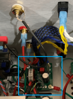
That board was sent with the first 2 VFET amp rounds. You could try to copy it, the schematic is around.
There is a PSFILT board and a TUBA board, both by Mark Johnson, that most are using. Those boards you have to have made yourself, or find someone with an extra.
Look for the ”Ship of Theseus” thread, it has the info for the PSFILT boards, and various input stage cards, of which you will need a pair. There might still be input stage card kits in the DIYAudio store.
The TUBA board is presented, and discussed in its own thread.
Well I looked in the swap meet for sale section and had no luck.
Are these add on PS boards absolutely necessary?
Are these add on PS boards absolutely necessary?
Quote:
Imho you could use this kit as an alternative
/Edit: could be, the 3A limit is too low. Sorry!
He probably could, depending on his output bias. I did. I used one of these in front of each channel, so 2 in total and hence no problem with the 3A limit. I did so on top of the existing small PS board the OP is looking for, the one that came with my very first VFET edition. That one is IMHO more appropriate to filter out lower frequencies. I haven't though assessed its sonic benefits alone (whereas I did for the additional SMPS filters) as it was part of the original kit, but my bet is the 2 additional SMPS filters followed by some additional PS caps at the OS board PS feed could do "most of the trick" re sound enhencement.
All what would be needed is a small basic DIY board to distribute the PS cables and feed the LED. Note that once there, you could also directly replicate the existing small board Papa designed., the one you want. The schematic is available and it is very very simple - perf board and job done...
Have fun
Claude
Need a pair or two ? https://www.diyaudio.com/community/threads/sony-vfet-2sj18.386205/#post-7034185
in case I wanted to try vfet 3 (both 2sk60 and 2sj18) without the front-end and with an input transformer, what load would the input transformer see? I need an input transformer as I use a pre with 100ohm balanced outputs ( and high voltage output, so maybe a 1:2 transformer is right)
schematis alone sez that Rin of OS is in range of 100K, but I don't know how much gate of VFet is hungry (never measured that nor I remember reading), so this is question for Pa
however, with Rout of 100R, increase that by squared voltage ratio of xformer, you're certainly good
however, with Rout of 100R, increase that by squared voltage ratio of xformer, you're certainly good
If you're feeling experimental, use a signal generator to apply a 2 volt square wave @ 1 kHz to the output card, through a 100K (1%) series resistor. Then look at the exponential risetime and falltime of the loudspeaker output, using an oscilloscope. Make sure you connect the scope GROUND to the VFET amplifier GROUND, which may or may not be the color of binding post that you expect (!!)
The exponential output will be
Vout = (amplitude) * (1 - exp(-1.0 * t / RC))
where "t" is time, "(amplitude)" is 2 volts, and "R" is 100 Kohms. Plug in two or three (Vout, t) datapoints measured from the scope face, and solve for "C". That's the input capacitance of the VFET output stage with no front end.
(You'll notice that "1 kHz" does not appear in the equation above. That's because it is only the repetition rate of the experimental setup. You can dial it up or down as you see fit, to make sure the output really does hit the asymptotes before switching again. Or to get the desired trace brightness on a older model, 100% analog, oscilloscope)
ZM and Mark Johnson, as usual, many thanks for your big help!
To Mark: theorically 2sk60 and 2sj18 have a ciss of 190pf; do you imagine that the vfet card can have very different values at different frequencies?
To Mark: theorically 2sk60 and 2sj18 have a ciss of 190pf; do you imagine that the vfet card can have very different values at different frequencies?
I have no experience with bare naked VFETs, sorry. All I know for sure is that when Nelson Pass was briefing me before I began the additional front end designs (Scourge, Bulwark, Marauder, Dreadnought) -- he told me that the 2SJ28 VFET output stage card was a very easy load to drive, and the Edcor PC600-15K transformer could do so effortlessly. He mentioned no numbers and I asked for none. Sorry!
I kind of half way remember seeing some thread titles on the Forum with tantalizing wording, like "VFET datasheets" and/or "SIT datasheets" or something. Don't know whether they were requests from people who didn't have a datasheet and wanted one, or let-me-share-my-bounty posts from people who did have a datasheet and wanted to spread it widely.
I kind of half way remember seeing some thread titles on the Forum with tantalizing wording, like "VFET datasheets" and/or "SIT datasheets" or something. Don't know whether they were requests from people who didn't have a datasheet and wanted one, or let-me-share-my-bounty posts from people who did have a datasheet and wanted to spread it widely.
- Home
- Amplifiers
- Pass Labs
- DIY SONY VFETS pt 3 - Got VFETs?