I see.....just checked the FE-boards. Both have R7 til Gnd/Chassis......so all good in my case.
Hello friends. In preparation of the arrival of the kits, I'm (as usual) trying to identify all that I need to do.
I plan to use the VFET amp together with the WHAMMY I use as headphone amp / preamp.
After I built my Whammy, there was discussion regarding additional in-series resistors added before the RCA outputs to raise the output impedance. I never did this, and have used it as is, connected to an ACA v1.0.
My setup has, in theory, a WHAMMY with a 1/10th ohm output impedance, currently hooked to a 10K ACA input impedance. Once I build the VFET, that would be a 1/10th ohm output impedance hooked to a 330K input impedance of the VFET FE.
Is this getting into difficult terrain here? Do you think there would be an issue or is that a precaution that is not likely to cause any troubles either here?
Thanks for any insight,
Rafa.
I don't see any reason you would want to add additional series output impedance to a good design like the Whammy. A small amount (e.g. 10Ω or a small coil with parallel resistor) is sometimes needed to keep a feedback amplifier stable into difficult loads (Wayne has probably commented on this, if not already baked it into the Whammy design). But otherwise, all it does is attenuate & increase sensitivity to parasitic impedances in your interconnect cables & the input Z of connected equipment.
I generally shoot for the lowest output Z I can achieve, without risking stability.
The input Z of the V-FET amp is pretty friendly - much lighter than the 10kΩ input Z of your ACA... Unlikely to cause a stability issue in your preamp, IMHO.
I generally shoot for the lowest output Z I can achieve, without risking stability.
The input Z of the V-FET amp is pretty friendly - much lighter than the 10kΩ input Z of your ACA... Unlikely to cause a stability issue in your preamp, IMHO.
Last edited:
Thanks for the detailed explanation. It mostly makes sense to me and my limited knowledge. Just a couple of clarifications: the Whammy was designed only as a headphone amp, the line output is an afterthought I implemented following community guidelines. Wayne did comment that they may not be needed.
As for the VFET input... yes, it is friendlier with its 300K ohms, but the range from 1/10th to 10K vs 1/10th to 330K is much wider. Not sure of that makes a difference for the better or for the worse.
Thanks again!
As for the VFET input... yes, it is friendlier with its 300K ohms, but the range from 1/10th to 10K vs 1/10th to 330K is much wider. Not sure of that makes a difference for the better or for the worse.
Thanks again!
Definitely for the better.
Capacitive loads are the nasty ones for feedback amps. The open loop output Z of the amplifier forms a pole with the load capacitance, which introduces phase shift at high frequencies. If that phase shift gets large enough, it can turn a stable feedback loop into an oscillator. IIRC, the Whammy output stage is a source follower, so open loop output Z should be pretty low to start.
Capacitive loads are the nasty ones for feedback amps. The open loop output Z of the amplifier forms a pole with the load capacitance, which introduces phase shift at high frequencies. If that phase shift gets large enough, it can turn a stable feedback loop into an oscillator. IIRC, the Whammy output stage is a source follower, so open loop output Z should be pretty low to start.
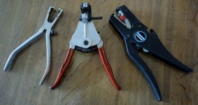
About wirestrippers for PTFE insulated wires.
I have a modern Stripax which is the black one to the right. It works not very well with this kind of insulation.
The old fashioned Beltzer to the left works every time if adjusted correct and also the next old fashioned but more fancy Beltzer tool in the middle works very well if there is a "groove" that fits the wire gage.
But which modern wirestripper that is more or less "automatic" works perfect with PTFE insulation?
Attachments
Thank you.....and not expensive.
The black Stripax on my picture is in the $100 range as far as I remember.
The black Stripax on my picture is in the $100 range as far as I remember.
I would like to find a reasonably priced source for 16ga PTFE coated hookup wire. The 100ft spools get a little pricey, especially after four colors worth.
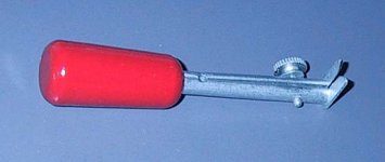

I have only ever seen 2 of these, both sent to me by Allen Wright and have never been able to find an on-line source. It is a Weller. It works fantastically.
dave
I love simple!! Looks like something a machinist could knock out pretty quickly.

Apex Jr.
Haven’t seen his new wharehouses but i did see what he had in 2000 and it was a real eye opener.
And i see Steve has managed to keep using the web site i hacked together for him
dave
Haven’t seen his new wharehouses but i did see what he had in 2000 and it was a real eye opener.
And i see Steve has managed to keep using the web site i hacked together for him
dave
16 AWG Gauge PTFE Wire Kit
https://www.amazon.com/dp/B072BCYL1...abc_1DAZBD6ZJVDZ5A08JP2S?_encoding=UTF8&psc=1
22 AWG Gauge PTFE Wire Kit
https://www.amazon.com/dp/B0727RGDS...abc_TYPHB9226YGFG1RAZNZF?_encoding=UTF8&psc=1
https://www.amazon.com/dp/B072BCYL1...abc_1DAZBD6ZJVDZ5A08JP2S?_encoding=UTF8&psc=1
22 AWG Gauge PTFE Wire Kit
https://www.amazon.com/dp/B0727RGDS...abc_TYPHB9226YGFG1RAZNZF?_encoding=UTF8&psc=1

- Home
- Amplifiers
- Pass Labs
- DIY Sony VFET pt 1