Nelson, I didn't intend to sound "cocky", I just wanted you to be able to intervene before hell breaks loose....
At ESS, we had a phrase, "What's a couple decibels among friends?"
🙂
At ESS, we had a phrase, "What's a couple decibels among friends?"
🙂
I'll have to remember that one.
I started getting interested in electronics in Junior High and became a license HAM. In High School, I came across the Cascode configuration and thought it would be the great foundation for an audio amp. Halfway through my design, out came the CAS so I moved on to other things. In undergrad, VFETs where just coming out and I managed to convince Motorola to send me a few for my senior project, another amp. Halfway into that design, you had yours so it evolved into a class AB digital switching amp (PWM where I had a pulldown channel and a pullup channel). This project got me my first job offer but instead I took a surprise offer to design hybrid digital/analog integrated circuits which took me in a different direction.
Bottom line is that our design ideas seemed to go in the same direction but you were always two (or more) steps ahead of me. This increased my admiration for your work.
I never lost my DIY spirit wherever I can which drives my wife crazy. I'm still dabbing in audio... Besides keeping my vintage stuff in peak working order, I designed and built a hybrid electrostatic/transmission line speaker. Oh, and just yesterday I finished recapping my NS-10.
Just a thank you for the years you kept our collective enthusiasm alive. Kudos again to the winners, I know we all realize how special this was.
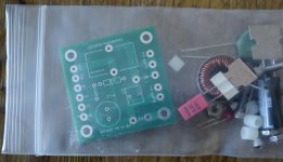
Parts kit arrived safely, seems complete. Has the correct boards ( c1 orientation). Chassis in transit from Italy. Will probably arrive next week. 🙂 🙂
What's the word on using the amp w/ 16ohm (nominal) speakers? I swear it was addressed but have no idea where. 3 different threads and searching for "16 ohm" in each not being an option makes for a difficult time. So anyone...16 ohm performance?
When Stereophile reviewed the SIT-3 and tried it with some 16 Ohm Zu's, they noted that it didn't sound quite right.
Papa suggested shunting with a 16 Ohm/10W resistor and it seemed to help in that case. Of course, that's the SIT-3, a different amp, but maybe there's similarities with the DIY Sony VFET in this regard too?
Papa suggested shunting with a 16 Ohm/10W resistor and it seemed to help in that case. Of course, that's the SIT-3, a different amp, but maybe there's similarities with the DIY Sony VFET in this regard too?
Thanks! That is what I thought I remembered reading somewhere in these threads. Just want to make sure it will be doable before I expend the (somewhat considerable) effort to haul out the horn speakers and set them up!
I never entered the first lottery, and congratulations to all that have been drawn. I plan to enter the 2nd lottery, too see what happens. I do have backup for some other designs that will be offered in the future. Everything happens for a reason🙂
Of course, that's the SIT-3, a different amp, but maybe there's similarities with the DIY Sony VFET in this regard too?
i remeber Nelson’s early on about the Sony VFET being a prima donna and being happiest with 8 ohms, and the Tonkin was happier with 16. I assumed this was nominal speaker impedance.
The bass section (<250 Hz) on my big MTMs sound fine on the SIT-3, but may hav estarted clipping earlier.
dave
When Stereophile reviewed the SIT-3 and tried it with some 16 Ohm Zu's, they noted that it didn't sound quite right.
Papa suggested shunting with a 16 Ohm/10W resistor and it seemed to help in that case. Of course, that's the SIT-3, a different amp, but maybe there's similarities with the DIY Sony VFET in this regard too?
just done it with my M2 ( my Vfet parts are still on the way) with a 22R on a Altec 16ohm woofer and i like it better like that , perhaps it also help to linearize it's impedance .. when you have no passive filter..
Posted more details on my possible application on the builder thread, but realised this section might be more appropriate for the central question...
Suppose you have enough gain to start with and want to try the VFET board in direct mode, that is without any front end module (well noting that the existing standard FE is also conveniently inverting phase and not just providing gain). Is my following understanding correct?
If you have wired the LS terminal exactly as intented /as in Papa's instructions (eg inversing LS connections INSIDE the chassis), and you want to run in direct mode, then all you would need to do to get both correct absolute phase and enjoyable "negative H2" out of the VFET amp section... would be to inverse the LS cables at the terminals (externaly). That is in fact equivalent to connecting the LS... as they would be in an usual amp.
Is my understanding correct?
If yes, a simple DPDT "ON- (nothing)- ON" quality switch per channel, hiding under the floor of the chassis, switching both lines of a single RCA connection in one go, could do the trick to switch between direct mode and usual FE + VFET mode... well noting that you would for the latter have to reverse again the LS cables at the terminals... or just accept positive H2 and inverting absolute phase in pure party mode if too lazy 🙂
Given the DC blocking input cap and high input impedance of the power board, I see no problem connecting directly a conventional source without dynamic or frequency response downsides. Am I missing something?
Thanks for your thoughts
Claude (thinking out loud a year after some H2 headache with B1K)
just done it with my M2 ( my Vfet parts are still on the way) with a 22R on a Altec 16ohm woofer and i like it better like that , perhaps it also help to linearize it's impedance .. when you have no passive filter..
Thanks for the note, I'll try this. I use 16ohm 414s run full range with the compression driver crossed in pretty high as recommended by Joe Roberts somewhere, so adding in a resistor should be easy. I actually made some adjustable crossovers (first order) that allow me to switch in different capacitor values and try different points. I could probably add some resistors in there for the purpose of making this play nice w/ the VFET amp.
Make that of course a 4PDT switch and not DPDT as you would need to switch on and off before and after the FE for a direct bypass...
Any thoughts?
Any thoughts?
What about a separate 10K:10K transformer inside the chassis for the switched connection bypassing the FE board? That would allow you to flip the polarity of the input signal and avoid impacting H2 polarity, speaker cable polarity etc. It would also allow you to use a balanced input (more volts.....).
Thanks for the answer 🙂
Why not, but soundwise a switch is better than a transformer... and way cheaper. Would allow me also to evaluate the sonic impact of the FE alone.
In this secondary system for our living room, I want negative H2 when doing nice listening sessions or most of the time - absolute polarity is a plus (not sure I am sensitive to that one on music). Party mode with lot of phones and many guests, who cares, in fact positive H2 is then likely to have slighty more density / impact (if reacting as the B1K).
Again, just thinking out loud to kill time, same as me looking at the chassis since a week, as my parts are due to arrive in May 🙂
Thanks again for the reply
Claude
yep can be 5k+5k:10k for gain but jfet buffer is goodWhat about a separate 10K:10K transformer inside the chassis for the switched connection bypassing the FE board? That would allow you to flip the polarity of the input signal and avoid impacting H2 polarity, speaker cable polarity etc. It would also allow you to use a balanced input (more volts.....).
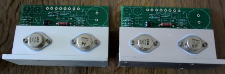
I picked up my kit today!
The VFET boards seems to be the production types with + close to the alu bracket.
The SMPS filter boards I never realized how to check if it is production or prototype but both will work well was my conclusion.....
The VFET boards seems to be the production types with + close to the alu bracket.
The SMPS filter boards I never realized how to check if it is production or prototype but both will work well was my conclusion.....
Attachments
I am not aware that there has been an "issue" with the filter boards...
That said I'll assemble my front-end board without fitting R7 even if I did receive the final production version.
That said I'll assemble my front-end board without fitting R7 even if I did receive the final production version.
It was something with a gnd/chassis connection.....which was not really needed as it was redundant....something like this 🙂
@ Meper
This chassis ground connection was with resistor on the FE cards.
Without R7 on the card is a prototype
This chassis ground connection was with resistor on the FE cards.
Without R7 on the card is a prototype
- Home
- Amplifiers
- Pass Labs
- DIY Sony VFET pt 1