

Oh wow, too many great chairs!
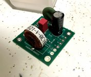
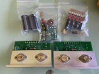
Here’s the completed PS filter board, which concludes the stuffing/soldering portion of my program. Next up will be some intensive studying of the wiring diagram and maybe getting some boards on the heat sinks.
My overall feedback so far is that everything has been easy to understand, organized well, and a breeze to assemble. Hope everyone enjoys their builds!
Ps. I received LSK170/LSJ74’s in my kit, and they all measured very tight matches. I wouldn’t sweat it if you didn’t receive the tiny Toshiba’s, as it’s obvious these have been matched well.
Attachments
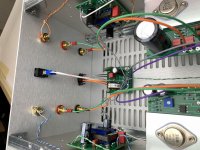
You can still zip tie, heat shrink, thermal cap, etc in this configuration. More important is to follow orientation on the silkscreen.
I thought Q1 and Q2 were supposed to face each others and zip tied for thermal tracking?
observe other Papamps, and orientation of JFets in them
Papa is not so much concerned with same, as regular Greedy Boy is
The M3's for the top/bottom cover are hex-types.....thread length about 10mm.
It will look "pro" compared to "philips-head" screws.....
+1 yes hex-types are the best

observe other Papamps, and orientation of JFets in them
Papa is not so much concerned with same, as regular Greedy Boy is
I haven’t realized that I got bad influence from the Greedy Boy.
 is for ..
@ V FETish
Yes super cool!
My winner kit amp is going to be half build by my friend Xavier and he is the final user.
We organise nano " Vfet Amp Camp" meeting at my home for soldering, adjustments etc. and music session.
For myself, I joint round 3 in August Greetings
Yes super cool!
My winner kit amp is going to be half build by my friend Xavier and he is the final user.
We organise nano " Vfet Amp Camp" meeting at my home for soldering, adjustments etc. and music session.
For myself, I joint round 3 in August
Greetings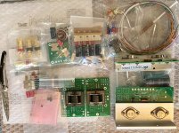
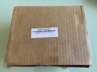
My VFET parts kit arrived arrived a day or two early. 😀
My chassis seems to have set up temporary residence in the Charles de Gaulle Fedex facility. 🙄
Thanks for parts kit photo 🙂 Incredible good Mr. Pass work

From France airport to USA transit can take 2 or 3 days
My VFET parts kit arrived arrived a day or two early. 😀
My chassis seems to have set up temporary residence in the Charles de Gaulle Fedex facility. 🙄
Deejo and Hafler

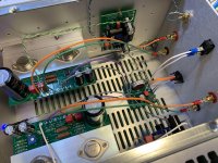
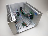
Next up will be some intensive studying of the wiring diagram and maybe getting some boards on the heat sinks.
With colours wiring picture find in Mr.Pass article another thing to savor
 Have a good time on the work bench
Edit: Check details on the high quality 6L6 photos if doubts
Attachments
Last edited:
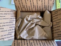
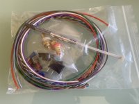
Parts arrived today.
Well packed, and sorted parts and boards in separate boxes and an envelope. Very clean and professional. I thought the color wiring in the pdf was for clarity, nope the silipplied wires are color coded.
A public thank you to the DIY Store team!
I did notice a date on the VFET alu plates, it would seem that this project has been incubating for a while already.
Now waiting on the chassis to arrive.
Attachments
-
 B8356ED9-4594-4C6A-8C21-EDB043783183.jpeg67.4 KB · Views: 292
 -
 421B1F0F-3792-4058-AAB4-7DBA390096CE.jpeg86.5 KB · Views: 290
 -
 C24839C1-E955-41E3-8318-2EC17E4385C3.jpeg100.3 KB · Views: 238
 -
 17FD1305-B530-4135-A914-87BC44827B11.jpeg123.6 KB · Views: 525
 -
 471707D8-9EDE-43DC-BD06-E08165DA3F4C.jpeg86.9 KB · Views: 251
Last edited:
- Home
- Amplifiers
- Pass Labs
- DIY Sony VFET Builders thread