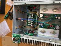
I would recommend placing the new filter board toward the rear of the amp so it doesn’t interfere with airflow and cooling of the output stage.
Thanks all. The heatsink area on my L'amp amplifier is a little smaller than this one - however of course there is only one device in that one, and this kit has two hot devices that need heatsinking.
Another member coincidentally lives close to me in Christchurch NZ, and he built this kit with the proper case. I saw and heard his build, while the heatsinks are larger on the proper case, they are about half the depth and also thinner overall. While that probably allows for more efficient heat dissipation, the heatsinks on my case are chunkier in general. So, heres hoping....
I will wire it up and fire it up, but thinking if the devices get close to 70 deg C, then I'll have to consider using a fan next....
I applaud on your progress as at one point you were not sure which way to go building this amp. Certainly shipping has gone really really expensive for larger heavier items. I no longer consider shipping anything large off AliExpress to NZ. As for the heatsink temperature, i've found with my building using the stock chassis, the fins are warm (never hot like in my CSX1) to the touch. Also don't be afraid to use a low tech analysis by simply touching around hot surfaces with your fingers. If the T-Bracket is toasty hot compared to the fins of the heatsink, then check the flatness of the mounting.
If you need access to any workshop tools, don't hesitate to let me know.

Bulwark with Jensen JT-123-FLPCH
Perseverance finally pays off.
This combination sounds amazing. Yes, it took me a while to get here due to a mistake in installing the coupling caps between the amplifier circuit and the signal transformer. Suffice to say that I saw physical proof of why the scoring lines are manufactured into the tops of electrolytic capacitors.
Now I can relax and enjoy the wonderful music. The Jensen transformers are worth every bit of extra cost and effort that it took to get them hooked up to the Bulwark circuit. They manage to achieve a balance of speed, detail and airiness without sounding harsh. The lower octaves are also effortlessly blended into the overall tonal balance. These characteristics are very much in common with the Edcor version of the boards. However, the Jensen transformers present even more detail and transparency. With these FE cards in place, the VFET amp sounds closer to my Aleph J than anything else. This is experienced as room-filling sound with as ease of presentation that invites extended listening sessions. What is also amazing is the precision of the 3-D imaging. The overall soundstage is forward in the same way as the original FE, deeper and taller overall. This is easiest to appreciate on simple ensemble recordings, and works on everything else too.
Maybe I just got lucky with my selection of the values for the RC network on the secondary side of the transformer. I picked 13.0k for R20 and 330 pF polypropylene for C9. C7 remains at 39 pF film, same as the Edcor version of this board. I used 3.32k at R22 and 1.30k at R21 for a gain of 3.55 from the amplifier. Total gain is 7.1 or 17 dB, not counting the insertion loss from the transformer. I kept the two primary windings in parallel and the secondaries in series. The signal inversion is performed at the secondary connection, so wiring connections to the OS are the same as with the original FE and the standard Bulwark build.
The main coupling capacitors are now an Elna Silmic 47uF, 35V at C2. These must be installed with the positive terminal connected to Q5 and Q6, which is with the short lead in the square through-hole. I have a Wima 0.33 uF polypropylene installed in parallel with the electrolytic at C3. Same tall red part as used on the original FE cards. This combination has settled in very nicely after a couple days of being run in. I used a Kemet A759 series Aluminum Organic Polymer 220 uF, 63V at C10. These values give very similar RC time constants to my previous version of the Bulwark circuit.
I highly recommend this modification.
New filter board
I mounted the new filter board as far back as I could -- Thanks for the reminder --- Install was pretty straightforward. Only one (ground) wire from the right front end board was a tad short -- but still worked ok. I'll live with the way it is vice having to pull the FE board, unsolder the ground lead, and then make the new GND wire about 2" longer -- just for appearance sake...
Amp is up and running and cooking in. So far, WOW!!
...Runs cooler, sounds better and scary quiet --- no thump ever!!
More later after the amp runs a while and I listen a bit more.
"Really" HappyJack
I would recommend placing the new filter board toward the rear of the amp so it doesn’t interfere with airflow and cooling of the output stage.
I mounted the new filter board as far back as I could -- Thanks for the reminder --- Install was pretty straightforward. Only one (ground) wire from the right front end board was a tad short -- but still worked ok. I'll live with the way it is vice having to pull the FE board, unsolder the ground lead, and then make the new GND wire about 2" longer -- just for appearance sake...
Amp is up and running and cooking in. So far, WOW!!
...Runs cooler, sounds better and scary quiet --- no thump ever!!
More later after the amp runs a while and I listen a bit more.
"Really" HappyJack
Attachments

Skilled and capable internet detectives will notice that post #747 of the lottery thread indicates diyAudio member HappyJack was a lottery winner on April 10th.
That means he got one of the first batch of VFET amps. The Pchannel VFET batch.
That means the VFET amp he installed the new power supply filter board into {message above this one} , was a Pchannel VFET amp.
That means the new power supply filter board has successfully eliminated power-on and power-off thumps, from a Pchannel VFET amp.
That means the new power supply filter board has successfully eliminated power-on and power-off thumps, from BOTH a Pchannel AND an Nchannel VFET amp. (see post #528 for that report).
The new thump calmer circuit seems to be performing reasonably well in early testing.
Test install: Theseus-PSFilter Board for Sony P-Channel VFET Amp, continued
I wanted to finish my thoughts on this filter board install and test.
First, a little background on me: I retired from the Research and Engineering department of a US Government facility in Eastern North Carolina 11years ago. That facility performs repair, rework, and maintenance engineering on Navy and Marine Corps aircraft. In my last job before retirement, I was director of a group of Requirements Engineers who developed new software and enhanced existing Operational software used for Time and Attendance, Supply Support, Logistics, and Just In Time manufacturing.
In my early career, I was a Navigation Electronics Technician for 7 years aboard a missile-carrying nuclear powered submarine (radar, Countermeasures, Navigation systems). After that, I taught electronics at Advanced Submarine School in New London, CT. Then came computer field service at a flight test facility in New York and then work in Pensacola FL with automated testing of avionics systems used aboard Navy aircraft and helicopters. So I am far from an Audio Engineering expert and I sure don't consider myself an audiophile either. But I sure enjoy having a system that can faithfully reproduce recorded music!!
So on that note, here are my observations on this filter board swap out:
1. Easy Peasy install -- provided one does not want to change up all of the wiring (folks may want to revisit post 300, 309, and 312 of this thread for a discussion about the pros and cons of using tinned leads, un-tinned stranded wire and ferrules when using the type of screw terminal used o this board)
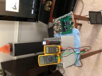
2. I got a real scare when I first powered up the amp with the new board installed. I had very few operational notes so I was not sure exactly what to expect from the de-thump circuitry. On power up, I got the treacherous blinking blue front panel LED. It continued to blink for at least 45 seconds while I worried that something was terribly wrong. But once the totally discharged capacitors charged up, the light turned steady and I went on to adjust the biases to 20 volts (the voltage read about 17 volts per side when I started with the new board -- but I did not check the bias voltage while the old board was installed so -- not sure if the new filter board caused the change or if the voltage was low beforehand) BTW, the DC voltage at the output of the filter board is 34.1 volts... Naturally, I forgot to check it before the board swap out. Also, the amp seems to be running cooler (around 125 degrees F vs: 138 Degrees F before the swap)
3. Bundling the wiring -- I opted to leave the leads from the filter board unbundled -- not knowing if bundling would cause any crosstalk -- so I left them au natural and spread out.
4. Thumps -- none. Though the thumps had been annoying, I was able to live with them. But now the only noise I hear from the amp is the audible mechanical click of the power on switch -- otherwise perfectly noise free...a nice plus
5. Sound quality...Remember, I'm a pragmatist, not an expert in sound -- but to my ears there was a very noticeable improvement in the sound out of this amp with the new board installed. In my opinion, that is the reason to do this swap out -- and you get rid of any thump as a bonus. I am feeding the Vfet amp with an ACP+ headphone/line preamp. I am feeding the ACP+ with an audio signal from either my iPad, my iPhone, or the Zone 2 preamp out from my home theatre amp (Thanks Tungsten Audio for the verbal kick in the tail to find a better way than using a speaker-to-line-out converter). The home theatre amp is fed optically from the bluRay/CD player, optically from my Apple TV box, via Airplay, or Pandora via internet from the Home Theatre player. So I do have a good variety of decent audio input sources.
6. I started out listening to some Jazz via Pandora (Dave Brubeck) as well as some classical via the BluRay player. With either source, the music reproduction was unbelievably exceptional. Keep in mind, I am playing this setup through a set of mediocre-at-best POLK 2-way 20-year-old speakers. The music out of this amp with this new filter board is well balanced, with attention-grabbing clarity of the highs (percussion, tenor sax, vocals), good strong mid range, and exceptional bass, especially considering the lackluster speakers. It may be me, but I really feel that the Vfet amp went from Great to Un-F****ing believable sound quality with the swap out of this board... forgive me for repeating myself as I say again that I'm not an Audiophile, just like to listen to good music well reproduced.
7. Keep in mind that your milage may vary and my 72-year-old ears may not be as critical as most of yours on the forum.
Thanks again to Nelson for creating this project and DIYAudio for using the lottery to offer folks the opportunity to experience the sound that this amp can reproduce.
And thanks one more time to Mark Johnson for involving me in this test drive.
Now I have to decide if I should put away the soldering iron and get out the table saw to start on the Elsinore speakers or leave that for a winter project and keep out the soldering iron to use on my BA2018 Line Amp kit.
...Back to the living room -- to turn off the TV and turn on this fine
"thump-less" "KICK-A**" system for a few more hours before bed.
HappyJack
post #528[/URL] for that report).
The new thump calmer circuit seems to be performing reasonably well in early testing.
I wanted to finish my thoughts on this filter board install and test.
First, a little background on me: I retired from the Research and Engineering department of a US Government facility in Eastern North Carolina 11years ago. That facility performs repair, rework, and maintenance engineering on Navy and Marine Corps aircraft. In my last job before retirement, I was director of a group of Requirements Engineers who developed new software and enhanced existing Operational software used for Time and Attendance, Supply Support, Logistics, and Just In Time manufacturing.
In my early career, I was a Navigation Electronics Technician for 7 years aboard a missile-carrying nuclear powered submarine (radar, Countermeasures, Navigation systems). After that, I taught electronics at Advanced Submarine School in New London, CT. Then came computer field service at a flight test facility in New York and then work in Pensacola FL with automated testing of avionics systems used aboard Navy aircraft and helicopters. So I am far from an Audio Engineering expert and I sure don't consider myself an audiophile either. But I sure enjoy having a system that can faithfully reproduce recorded music!!
So on that note, here are my observations on this filter board swap out:
1. Easy Peasy install -- provided one does not want to change up all of the wiring (folks may want to revisit post 300, 309, and 312 of this thread for a discussion about the pros and cons of using tinned leads, un-tinned stranded wire and ferrules when using the type of screw terminal used o this board)
2. I got a real scare when I first powered up the amp with the new board installed. I had very few operational notes so I was not sure exactly what to expect from the de-thump circuitry. On power up, I got the treacherous blinking blue front panel LED. It continued to blink for at least 45 seconds while I worried that something was terribly wrong. But once the totally discharged capacitors charged up, the light turned steady and I went on to adjust the biases to 20 volts (the voltage read about 17 volts per side when I started with the new board -- but I did not check the bias voltage while the old board was installed so -- not sure if the new filter board caused the change or if the voltage was low beforehand) BTW, the DC voltage at the output of the filter board is 34.1 volts... Naturally, I forgot to check it before the board swap out. Also, the amp seems to be running cooler (around 125 degrees F vs: 138 Degrees F before the swap)
3. Bundling the wiring -- I opted to leave the leads from the filter board unbundled -- not knowing if bundling would cause any crosstalk -- so I left them au natural and spread out.
4. Thumps -- none. Though the thumps had been annoying, I was able to live with them. But now the only noise I hear from the amp is the audible mechanical click of the power on switch -- otherwise perfectly noise free...a nice plus
5. Sound quality...Remember, I'm a pragmatist, not an expert in sound -- but to my ears there was a very noticeable improvement in the sound out of this amp with the new board installed. In my opinion, that is the reason to do this swap out -- and you get rid of any thump as a bonus. I am feeding the Vfet amp with an ACP+ headphone/line preamp. I am feeding the ACP+ with an audio signal from either my iPad, my iPhone, or the Zone 2 preamp out from my home theatre amp (Thanks Tungsten Audio for the verbal kick in the tail to find a better way than using a speaker-to-line-out converter). The home theatre amp is fed optically from the bluRay/CD player, optically from my Apple TV box, via Airplay, or Pandora via internet from the Home Theatre player. So I do have a good variety of decent audio input sources.
6. I started out listening to some Jazz via Pandora (Dave Brubeck) as well as some classical via the BluRay player. With either source, the music reproduction was unbelievably exceptional. Keep in mind, I am playing this setup through a set of mediocre-at-best POLK 2-way 20-year-old speakers. The music out of this amp with this new filter board is well balanced, with attention-grabbing clarity of the highs (percussion, tenor sax, vocals), good strong mid range, and exceptional bass, especially considering the lackluster speakers. It may be me, but I really feel that the Vfet amp went from Great to Un-F****ing believable sound quality with the swap out of this board... forgive me for repeating myself as I say again that I'm not an Audiophile, just like to listen to good music well reproduced.
7. Keep in mind that your milage may vary and my 72-year-old ears may not be as critical as most of yours on the forum.
Thanks again to Nelson for creating this project and DIYAudio for using the lottery to offer folks the opportunity to experience the sound that this amp can reproduce.
And thanks one more time to Mark Johnson for involving me in this test drive.
Now I have to decide if I should put away the soldering iron and get out the table saw to start on the Elsinore speakers or leave that for a winter project and keep out the soldering iron to use on my BA2018 Line Amp kit.
...Back to the living room -- to turn off the TV and turn on this fine
"thump-less" "KICK-A**" system for a few more hours before bed.
HappyJack
Attachments
I applaud on your progress as at one point you were not sure which way to go building this amp. Certainly shipping has gone really really expensive for larger heavier items. I no longer consider shipping anything large off AliExpress to NZ. As for the heatsink temperature, i've found with my building using the stock chassis, the fins are warm (never hot like in my CSX1) to the touch. Also don't be afraid to use a low tech analysis by simply touching around hot surfaces with your fingers. If the T-Bracket is toasty hot compared to the fins of the heatsink, then check the flatness of the mounting.
If you need access to any workshop tools, don't hesitate to let me know.
Thanks Super.
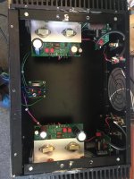
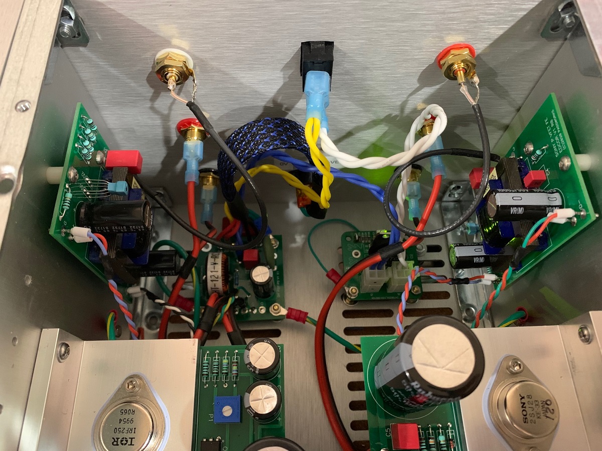
Got my amp up and running. Sweet, Im pretty happy with it. Set it up to +20VDC and ran it for 15 mins or so. The LH side VFET is getting about 5 deg C warmer than the RH side one, as its more tucked behind an internal heatsink fin I suspect.
Still, the VFETs arent getting any hotter than 42 deg C and 38(ish) deg C respectively for the LH and RH sides. Im measuring with a laser thermometer.
Sounds great. I was even able to install Super Through speaker caps (after this pic was taken) and the SMPS still ran fine. I'd just like to roll the input cap now.
At some stage I'd also like to install a linear PSU (what secondary voltages in a trafo would we look for, around 25VAC x 2?)
Attachments
Last edited:
Thanks Happyjack
Sad you didn't measure / adjust bias before.
Whereas the PS voltage is unlikely to have changed in a significant way by this filter, the voltage bias does a lot to the sound. Reading your findings (temperature, sound signature etc.), some of it is likely to be due to the 17V vs 20V voltage bias. EDIT: I said likely, not affirming anything of course.
Not saying the filter isn't good or else, just raising this point and again thanks for all this
Enjoy music
Claude (who has still yet to build his 2 SMPS filters, shame on me)
Last edited:
Wow, THANK YOU HappyJack! That's quite a thoughtful and comprehensive review. I'm thrilled that the new board performed nicely in your amplifier.
Back on post 1000, I also showed a simple and effective anti-thump/pop circuit using a soft start SSR and an NTC. When the amp is turned on, current is forced through a resistive NTC to slow down the ramp up. Once it reaches steady state, a solid state relay (SSR) connects and bypasses the NTCs.
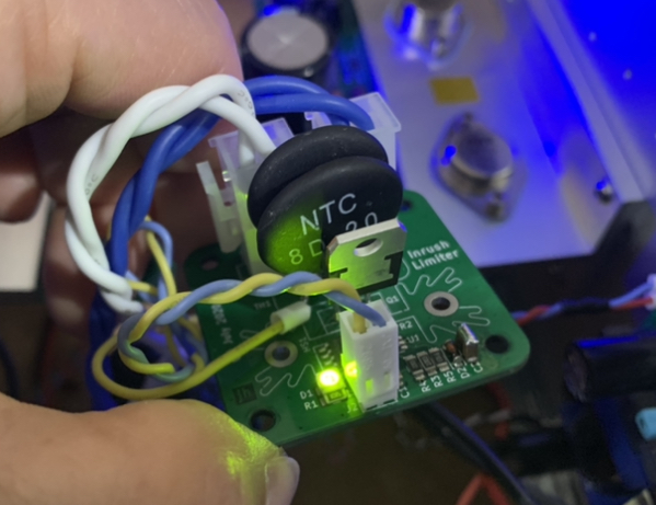
Gerbers are freely available if anyone is interested. I think I’ll ask Jhofland to make a through hole version of this board and it is an easy build. It’s handy for soft starting almost any single rail SMPS to an amp to prevent thump and hiccup starting.
Schematic:
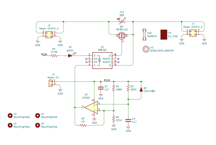
It’s quite compact and let’s you use your existing compact CLC filter board and mounts in between the filter board and the power switch. Most importantly, you won’t have to move your output stage heatsinks to make room.
Gerbers are freely available if anyone is interested. I think I’ll ask Jhofland to make a through hole version of this board and it is an easy build. It’s handy for soft starting almost any single rail SMPS to an amp to prevent thump and hiccup starting.
Schematic:
It’s quite compact and let’s you use your existing compact CLC filter board and mounts in between the filter board and the power switch. Most importantly, you won’t have to move your output stage heatsinks to make room.
Last edited:
I don't quite see how an inrush current limiter helps prevent VFET amps from thumping at switch-off.
Several members have reported annoyingly loud pops, bangs, and thumps at switch-off, on both Pchannel and Nchannel versions of the VFET amplifier. Indeed most people with thump problems say the switch-off thump is much worse than the switch-on thump, at least on their amplifier with their speakers.
Several members have reported annoyingly loud pops, bangs, and thumps at switch-off, on both Pchannel and Nchannel versions of the VFET amplifier. Indeed most people with thump problems say the switch-off thump is much worse than the switch-on thump, at least on their amplifier with their speakers.
P channel VFET here...
Completely negligeable pop despite 98dB/m/W efficiency LS, and indeed only at switch off. And sometimes (or it is so quite that I don't notice it the other times). Nothing whatsoever at switch on. Tha ddition of PS caps didn't really change a lot of things.
No concern for me TBH... but then again P channel VFET.
Claude
yep only on N ,v2 ones that's why Pa put in relay ...and He suggest a mod for ultrafast activation .just do be happy
To get rid of the random "flicker noise" from one of the VFETs in my amp (which can go as high as 20 mV bursts) I try to get a new pair of 2SJ28.....from "somewhere".
Does is matter if it is a KE-33, KD-33 or KF-33 type?
I guess not....?
Does is matter if it is a KE-33, KD-33 or KF-33 type?
I guess not....?
Sounds good if the bias circuit on amp board can handle all types.
If anybody knows a good source of these VFETs I would like to know.
I have written to "Prasi" (via ebay) but no response so far.....
If anybody knows a good source of these VFETs I would like to know.
I have written to "Prasi" (via ebay) but no response so far.....
- Home
- Amplifiers
- Pass Labs
- DIY Sony VFET Builders thread