Hi Tungsten,
Great input of yours regarding all the various FE options...
Given your experience, and eventhough everyone has different ears and should experiment these FEs by himself, I believe it would be of added value if you would summarise for all FEs all your findings re sonic signature vs the reference everybody shares, that is the original FE by Papa.
Something with the plus and minus, or differences if... different rather than a + or a -, and idealy also a scale for the magnitude of the sonic change as you perceived it. As a reference for this impact / magnitude change you could for example use a well known reference, big enough for everyone's ears, perhaps the magnitude of change occasioned by the additional PS caps you recommended...
All this could help future builders and also encourage other members to share their experience as this may vary (tastes and colours) - which is also good as that way not only the initialy recommanded FEs get all the light and possibly all options are tried in a way or another by a bunch of members...
Just thinking out loud
Many thanks again for all what you did
Claude
But the H.M.S. Relentless in fact existed.......so that will be the perfect name for the Relentless input board......if it will ever be "released"....
There will be so many of these front-end boards that you will be able to keep yourself busy for a very long time even if you can’t obtain Relentless.
At last count there’s 9, I think, and one of those has 8 distinct variations in and by itself... so the toybox will be quite deep and fun.
At last count there’s 9, I think, and one of those has 8 distinct variations in and by itself... so the toybox will be quite deep and fun.
Yes, but most seems quite "complicated" and I like the simplicity. I also like the sound of "original" amp with JFET PP driver for Edcor.
Relentless looks also quite simple in design and "advertised" as something very special. Layout of PCB also looks nice.....
Relentless looks also quite simple in design and "advertised" as something very special. Layout of PCB also looks nice.....
A closer look at "Relentless" shows that the active component is a 5-pin SOT-23.....so probably a 5-pin op-amp?
TSOT-23 the package is called also?
At least they exists......like this one:
https://docs.rs-online.com/baef/0900766b810ed950.pdf
I learned something new today........
TSOT-23 the package is called also?
At least they exists......like this one:
https://docs.rs-online.com/baef/0900766b810ed950.pdf
I learned something new today........
Sounds like you'll need to come to Burning Amp a day or two early and ingratiate yourself to Mark. Maybe you could host a dinner party or something. 🙂
Yes, that could be fun.....at least I know the area from some trips years ago to SF. Lombard Street was fun to drive but only with an automatic gear box car that can hold the car steady while you are looking at the sky. The old Victorian houses were very nice also but still a "steep" price I guess. But they could be nice for a dinner party?
Tuba filter installed and tuned. Pots on main boards readjusted to 20v. I’ll give the Tuba & Marauder combo a run later tonight. Thanks for all the great work Mark!!!!
Attachments
Fantastic job, Randy! VFET amp owners, especially those with N-channel output stages, will be eager for your listening evaluations about (a) audible hum reduction, (b) turn-off thump elimination, and of course (c) changes to the sonics.
Oh and the "PLEASE remove the 100 Hz spikes from my FFT" gang might possibly have a couple of breathless inquiries too. They're intrigued by the dual independent voltage regulators @ 2.2 amperes apiece.
Oh and the "PLEASE remove the 100 Hz spikes from my FFT" gang might possibly have a couple of breathless inquiries too. They're intrigued by the dual independent voltage regulators @ 2.2 amperes apiece.
True Mark, that sums it up nicely,😀. "C" is especially important as my VFET amp is very quiet already.
Hey guys
I have bought the front end kits from the store and have my Vfets ,Where can i get the output boards and power supply's please
Cheers
I have bought the front end kits from the store and have my Vfets ,Where can i get the output boards and power supply's please
Cheers
You may amuse yourself by building the front end kits as you wait for the new output stage boards to show up in the store. Papa’s announcement was only two days ago.
There has not been an announcement regarding the chassis for the VFET pt 3. The Dissipante Deluxe 4U has the correct size heat sinks, pre-drilled for mounting the boards.
There has not been an announcement regarding the chassis for the VFET pt 3. The Dissipante Deluxe 4U has the correct size heat sinks, pre-drilled for mounting the boards.
Ahh great thanks ,I thought i had missed outYou may amuse yourself by building the front end kits as you wait for the new output stage boards to show up in the store. Papa’s announcement was only two days ago.
There has not been an announcement regarding the chassis for the VFET pt 3. The Dissipante Deluxe 4U has the correct size heat sinks, pre-drilled for mounting the boards.
@claudeSOME THINKING RE SMPS FILTERING for the VFET amp
(sorry, quite long, skip if boring 🙂
The filter that comes with the VFET kit is a 2nd order filter with Fc = 460Hz. Quite nice.
The SMPS that comes with the VFET is not very well documented regarding output ripple and noise, nor what output filter it has built inside already at its output, so it would be handy at least to plug a (good) scope and measure what comes out. Enters Mark Johnson, who elsewhere pointed to the existence of Meanwell test reports, and although we don’t get the figures in written we can find on those…some nice oscilloscope captures regarding ripple and noise. Handy. It appears that this SMPS seems to produce some LF ripple and noise (at twice the main’s frequency probably) and some HF ripple and noise, that seems to have its main component at a tad under 200kHz - and some much higher frequency components with a very low amplitude - presumably related to the intrinsec operating frequency of the SMPS. I chose to focus on LF = say 100Hz ish, and HF = say 200kHz.
Let’s see how to tackle both. I know some will argue that the 200kHz ripple and noise are well outside the audio band, but IME they do impact audio a way or an other. And I trust my ears on that, more than any of my diplomas, privilege of what came first LOL.
The LF can’t really be addressed easily unless you build a filter with a very very low Fc. Could be done, but in our application « may » have some downsides re dimensions/integration or voltage losses and cost. On the other hand, I am not sure it would get me anywhere as the addition of large output capacitors could exactly address this in a possibly suffisant manner. I don’t know how the existing SMPS filter addresses this already, but it probably does to some extend due to its 1000uf output cap. Anyway, my idea is to add one 1500uF cap betwen +V and G on each OS board, feeding the OS board (and, as ever, the related FE board). That should help the LF ripple, should it be needed. And the HF ripple as we shall see.
The HF ripple is indeed somewhat addressed by these additional caps. Depending on how you model it, you can (simplifying a lot) either consider that the existing 2nd order filter has now Fc = 230Hz. Or you can consider that due to the extra cabling, you have added for each channel a RC 1st order filter after the existing filter. Taking 0.02R as the cable resistance (pure guess work), that second filter would have Fc = 5kHz. I like that model, shows some better channel separation and the resulting filter is the sum of 2 filters, so you just add slopes on a bode diagram where appropriate, albeit I am not sure that at 200kHz the 1500uF caps are still at their best. In real life, the filter has a less schematic response (starting of course earlier than Fc, more rounded off around Fc, and ultimately it has a finite filtering response capability – I don’t really know what to think of figures below -60dB in my DIY filtering works), or perhaps even worst a downgraded response at very HF. But anyway, as far as we are concerned, we get already a reasonable filtering job done at 200kHz anyway, be it thanks to Papa’s filter.
Nevertheless, we could go further and try different things. The VFET can tolerate some marginal voltage feed losses, so why not adding a low DC resistance SMPS filter that has a solid pedigree and that trully worked well even in optimised set ups ? One that is made for that, one that has been designed by someone skilled who probably took a lot of time to hone it: Mark’s PO89ZB. I have a dozen of these and they are amazing SMPS filters. They are also non expensive and with a small form factor, handy for integration. Problem is they are designed for up to 3A and 48V, and probably work trully well when quite within their current limit. Sadly, the VFET amp draws a bit more than 3A, but then one channel only… 1.6A. Hence putting one of these filters betwen the existing filter board (that I consider really as a remote final part of the existing SMPS) and each OS board feed (right before « my » additional 1500uF caps). Problem solved, and we get now an additional 4th order filter with Fc = 5kHz… and negligeable voltage losses regarding the PS (may perhaps check the bias in case it needs a marginal touch of adjustment, just in case ?).
As a side note, the B1 Korg has in my case (later caps increase) as main feed a very good 2nd order RCRC filter with Fc = 7Hz (!) - and yet it still benefitted from the PO89ZB filter, possibly due to very HF content…
Regarding HF filtering, I see « my » entire chain taken from the output of the SMPS as :
- a standart 2nd order filter with Fc = 460Hz (and HF filtering capable)
- a channel feed separation
- a 4th order filter with Fc = 5kHz (and very HF filtering capable)
- a 1st order filter with say Fc= 5kHz (and barely HF filtering capable, just a bonus from our LF work)
Or perhaps (neglecting the filter’s output cables) as :
- a standart 2nd order filter with Fc = 460Hz (and HF filtering capable)
- a channel feed separation
- a 2nd order filter with Fc = 5kHz (and very HF filtering capable)
- a 2nd order filter with Fc= 2.4kHz (and very HF filtering capable)
Whatever, quite something promising to… try, of course, as only the sonic result matters.
Regarding LF, we get of course all this aswell but given the various Fc we are considering, we can IMHO safely ignore the filtering capabilties for LF. Nevertheless, we have added quite some extra capacity to help the LF ripple. If we consider only this very limited section of the amp, we moved from 1000uF for both channels to the said 1000uF for both channels with the addition of 2x 470uF + 1500uF = 2440uF per channel. Some additional R in the line indeed, but lower ESR cap at the end in direct feed anyway. That should help quite a bit LF ripple and noise, should it ever be needed and LF response aswell hopefully. So from 1000uF to 5880uF in total for the entire VFET amp.
As a side note, I have seen in Class D amps similar SMPS firing up without any problem - and without « benefitting » from many time constants due to Ls and Rs ‘in the way’- with 6000uF of PS caps and even over 9000uF, so the SMPS hiccup safety should hopefully not trigger… Fingers X.
Let’s see if in real life all that makes sense or… changes nothing or even ends up being worst LOL !
Nest step is the addition of the two 1500uF caps on the OS boards, probably followed by the installation of the 2 SMPS filters.
Claude
Please could you post or link to the schematic for the VFET kit is a 2nd order filter with Fc = 460Hz?
Is the attached pic?
TIA
Felipe
Attachments
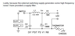
The above attached pic is the schematic of the SMPS filter used with the first set of VFET amps issued by N. Pass and the diyAudio store. It is a second order filter (even with the leading 0.33 film cap) by virtue of the small inductor feeding the 1000 uF output cap. I used this filter board for a while in my VFET amp before building a separate linear supply. It works well enough for the P-channel VFET, but may need to be augmented for the N-channel version.
Thanks Claude, I'm powering a laptop that needsds 4A
Following your idea I made 50uH 2200uF 50uH 20uF, sounds very good.
Following your idea I made 50uH 2200uF 50uH 20uF, sounds very good.
- Home
- Amplifiers
- Pass Labs
- DIY Sony VFET Builders thread