I have built my Marauder boards as well, they dialed in perfectly and look very good on the scope, in isolation. Perfect square waves, with just the tiniest bit of 50kHz barely discernable in the rising flank at high temporal resolution. Bandwidth approx. 2.7 Hz to 1 MHz.
Plan to install them tonight or tomorrow night - really excited to hear them !
I have also used WIMA FKP2 for the pF caps, and so far the black Panasonic for the 2.2 uF film caps. Let's see how the boards sound; maybe trying some 2.2 uF MKC caps instead later on. How critical is the 2.2 uF figure - would, say, 1.5 uF work well as well ?
Regards, Claas
Attachments

That is a good looking pair of boards.
A value of 1.5 uF should be fine at C3. I would not recommend going any lower.
If you want to reduce the minor 50 kHz PS ripple, try substituting a small 10 uF, 100V electrolytic at C21. That’s how I have mine set up now.
A value of 1.5 uF should be fine at C3. I would not recommend going any lower.
If you want to reduce the minor 50 kHz PS ripple, try substituting a small 10 uF, 100V electrolytic at C21. That’s how I have mine set up now.
Hi TungstenAudio,
thanks for your reply ! As a follow-on question: did you bypass the non-polar caps C8 and C10 in your build ?
I really like Nichicon's UES (un-bypassed), but they are too large here, resp. not available in the necessary voltage rating, so I used the recommended Nichicon VP / EP, so far un-bypassed.
Regards, Claas
Yes, I bypassed both C8 and C10 with Wima 0.47 uF, 63V MKS caps on the underside of the board. For C10 I used Nichicon 47 uF, 35V ES series. This is a sufficient voltage rating for that location. The Boosted voltage rail does not exceed 58V, and the OPA552 will never output more than half of that. For C8 I used the Nichicon 220 uF, 50V EP series that came with the kit.
As a side note, a value of 47 uF is far more than necessary for C10. If you wanted, you could try using one of your 1.5 uF film capacitors at that location. If you prefer to stay with a larger value bi-polar electrolytic, then values as small as 4.7 uF or 10 uF will be quite sufficient, and easier to find in a 50V rating.
As a side note, a value of 47 uF is far more than necessary for C10. If you wanted, you could try using one of your 1.5 uF film capacitors at that location. If you prefer to stay with a larger value bi-polar electrolytic, then values as small as 4.7 uF or 10 uF will be quite sufficient, and easier to find in a 50V rating.
If you want to reduce the minor 50 kHz PS ripple, try substituting a small 10 uF, 100V electrolytic at C21.
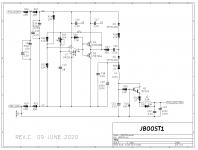
I recommend doing a little bit of pencil and paper exploration first.
Start by analyzing the (R29 - L1 - C21) attenuator. (a) What's the LPF corner frequency of (R29 , C21) only -- assuming L1 isn't even there; assuming L1 is replaced by a short?
(b) What's the LPF corner frequency of (L1 , C21) only -- assuming R29 isn't even there, assuming R29 is replaced by a short?
(c) What do you get when you assume all three components (R29 - L1 - C21) are in place? How many dBs of attenuation do these three components provide, at 50 kHz and the harmonics of 50 kHz? { perhaps use circuit simulation to double check your arithmetic }
(d) What's the LPF corner frequency of (R27 , C19)? { assuming D9 is an ideal diode }
(e) Now repeat actions (a), (b), and (c) for the (R31 - L2 - C23) lowpass filter.
(f) What's the total attenuation at 50 kHz, from Q1 emitter to POS_BOOSTED ?
_
Attachments
Last edited:
Yes, I already did part (b). It suggests a significant reduction in Fc and a corresponding reduction of the 50 kHz switching frequency and its odd order harmonics. After that, I let my ears tell me what sounds best. I'm weird that way.
In a different line of thought, I've decided that I like the HV opamp enough to try it in other applications. The sound of the OPA552 as implemented in the Marauder is far superior to the sound of the OPA604 in the Tuscon front end for the M2x. So I am thinking about building a simple OPA551 front end for my F6, to try in place of the Austin-inspired Diamond Buffer that currently resides in that amp. (The OPA551 is a unity gain stable version of the OPA552.)
I've just sent out the Ship of Theseus (post #1283 in this thread) kit to a volunteer beta-tester. Hopefully it goes together easily and produces a pleasing sound.
After using my Dreadnought cards as testbeds for understanding and tweaking the JBOOST sub circuit, I finally installed them back into the amp for some extended run-in and listening. The JBOOST tweaks were left with the switching frequency set to 78 kHz, and L1 changed to 220 uH. I also replaced the film output capacitor with an Elna Silmic 100 uF, 50V electrolytic, bypassed with a 0.47uF PET film cap. This combo has worked well on some of my other cards, so I decided to give it a try here as well.
It took nearly 100 hours of run time for this configuration to settle in. I realize that may seem excessive, but the sonic character and balance continued to shift for longer than usual. I left the amp on overnight once after a couple days of listening on and off, and it sounded noticeably smoother the next day. It was definitely worth the wait. The Dreadnought cards now have a fine combination of smoothness and transparency. The detailed presentation throws a soundstage above and beyond my speakers. Nearly as holographic as the Marauders, which are the top performers in this area so far. I’ve spent some time listening to some albums that I haven‘t put on for a while, and have been hearing details that I hadn’t noticed before. The VFET amp is great at this, and the Dreadnought cards do a great job of getting out of the way..
It took nearly 100 hours of run time for this configuration to settle in. I realize that may seem excessive, but the sonic character and balance continued to shift for longer than usual. I left the amp on overnight once after a couple days of listening on and off, and it sounded noticeably smoother the next day. It was definitely worth the wait. The Dreadnought cards now have a fine combination of smoothness and transparency. The detailed presentation throws a soundstage above and beyond my speakers. Nearly as holographic as the Marauders, which are the top performers in this area so far. I’ve spent some time listening to some albums that I haven‘t put on for a while, and have been hearing details that I hadn’t noticed before. The VFET amp is great at this, and the Dreadnought cards do a great job of getting out of the way..
Although I was a little late to the party I did finish my VFET (P channel) a few weeks back. Shame on me for not stopping to say THANK YOU earlier. During assembly I was blown away by effort and man hours that went into putting together a limited addition amplifier kit. I know we have a fearless leader, but this project is obviously a huge team effort. I feel blessed to have the opportunity to build and listen to a this project...It's quite an honor. Oh, and it sounds pretty good too😉
I'm very happy that builders enjoy the sound of Dreadnought and Marauder. The transformer-less design approach appeals to at least some VFET owners, which is delightful. I kind of doubt that Nelson Pass expected to see front end designs with DC-to-DC converters and gain-of-5x amplifiers, instead of step-up transformers. But here they are, and some listeners actually prefer them. Who would have thunk it?
(at full output power / onset of output stage clipping, the front end's output waveform swings 41 volts from peak to trough -- but the power supply is 36 volts)
(at full output power / onset of output stage clipping, the front end's output waveform swings 41 volts from peak to trough -- but the power supply is 36 volts)
What I like with original VFET is that it is extremely silent. I guess you compromise this a little if you use an active voltage gain device rather than a passive like the Edcor (assuming Edcor is kept away from magnetic fields)? <-- Edcor will only amplify the very little noise from JFETs but also act like a small filter?
Or how is "hiss noise" performance with the transformer-less gain stages?
Original VFET has almost no hiss-noise in tweeter (94 dB).
Or how is "hiss noise" performance with the transformer-less gain stages?
Original VFET has almost no hiss-noise in tweeter (94 dB).
The amplifier gain cards are just as silent as the transformer gain cards. (I have built all four.) There is no detectable noise from any of them.
The NP original front end with 2SK170+2SJ74+EdcorTransformer is silent too. So is Relentless, another front end with an Edcor.
_
_
Last edited:
What makes it "Relentless"?
I can spot only one active device.......a single JFET?
So it is a single ended driver for Edcor?
What is TungstenAudio's comment to this input board?
It is not part of the DIY-boards for the VFET amp?
Some of the M2X input boards were more silent that other.......therefore my question about "silence"......
The first five VFET front end cards not designed by Nelson Pass, were named for British warships. There's a Forum thread dedicated to discussing them, link below.
The dedicated Forum thread is here:
https://www.diyaudio.com/community/...ught-front-end-cards-for-diy-vfet-amp.370389/
etc
The dedicated Forum thread is here:
https://www.diyaudio.com/community/...ught-front-end-cards-for-diy-vfet-amp.370389/
The Relentless FE card is much more of a limited edition model. I have not had the opportunity to build or listen to it.
I believe there is more than one active device, but can't really speculate what that is. I'm sure it sounds very nice...
I believe there is more than one active device, but can't really speculate what that is. I'm sure it sounds very nice...
- Home
- Amplifiers
- Pass Labs
- DIY Sony VFET Builders thread