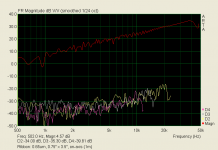
Indeed 🙂...At 2kHz 1A results in 81dBSPL, this is 6 dB more than the minimal ribbon....Not bad, not bad at all 🙂
Congrats on another successful build.
I noticed the top end of your recent measurements don’t have the -12dB/oct slope of your earlier measurements in post#2.
Were you finally able to figure out what was causing that HF roll off?
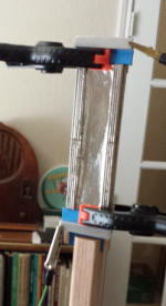
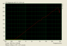
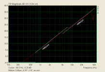
Getting the 0.65µm ribbon cut and mounted took some patience, but I was rewarded with an essentially perfect match with the theoretical +6dB/oct slope to the 40kHz limit of the B&K 4133 mic. The small step where response transitions from dipole loss to directivity gain is due to the response following the step put in the radiation impedance(acoustic load on the ribbon) by the small baffle formed by the magnet structure. Usually the mass of the ribbon dominates the acoustic load so the step is not seen....I hope to get some measurements with the aluminum leaf this weekend. I did measure the thickness using a few different methods and multiple layers. On average it is 0.65µm thick.
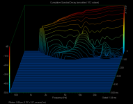
CSD looks quite clean. In fact listening to pink noise or MLS test pulses reminded me more of listening to an ESL than a ribbon...no colorations or extra “sparkle” at all…just smoooooth sounding like the ribbon is caressing the air. 😉
I hope to try the JonasKarud lamination technique with thicker aluminum foil to see how it compares.
Distortion performance was not stellar, but reasonably low and constant across the useable range. Better magnet geometry (a la Gerrit Boers) could not doubt improve this. I noted that the amplifier I was using contributed ~0.1% of that distortion. I guess it is not exactly happy about being asked to drive a 2 ohm load.
Attachments
@Bolserst Looks amazing! I have to be honest, i didn't think that you could suspend ribbon that is that thin and that it will survive currents through it. Thanks for measurements, now we have benchmark to compare to.
Only problem that I see is that mounting that thin foil in dipole configuration is disaster waiting to happen - small wind can destroy that membrane easily.
If you have time, try embossing alu membrane and see if it is any stiffer. May improve distortion also...
@Jonas You don't have to waste time. Just write in one sentence.
@ Everybody What measurement mics are you using, and what do you recommend?
Thank you 🙂Indeed 🙂
Congrats on another successful build.
I noticed the top end of your recent measurements don’t have the -12dB/oct slope of your earlier measurements in post#2.
Were you finally able to figure out what was causing that HF roll off?
No I didn't change anything and still don't know the reason for the drop off.
Great work with the ultralight ribbon

Nice to see theory in action this way.
I played around with the filter some more,red is without and blue with DSP:

I used two shelfs and two notch filters.
The respons for several different angles:

Notice how the response is still smooth at 85 degrees.
regards,
Gerrit
Everybody is making great progress! (Except me😱). Thanks for sharing the results. The latest versions from Gerrit and Bolserst are inspirational.
Bolserst: If it wouldn't be a major pain, could you provide some dimensions from the original Neo 8s that went south on you? I'm trying to build a planar magnetic system and knowing what the pros have already made work would be very helpful. The information I have in mind includes things like
Thanks.
Few
Bolserst: If it wouldn't be a major pain, could you provide some dimensions from the original Neo 8s that went south on you? I'm trying to build a planar magnetic system and knowing what the pros have already made work would be very helpful. The information I have in mind includes things like
- magnet dimensions
- magnet spacing
- magnet-to-diaphragm spacing
- conductor thickness
- conductor width.
Thanks.
Few
I know I have the first 3 items written down somewhere, will take a look tonight. I didn’t measure conductor thickness/width, but did measure the mass of the whole diaphragm/conductor combination. Knowing the total mass, the DC resistance of the whole conductor length, and estimating trace width from the picture should get you close to the thickness.…If it wouldn't be a major pain, could you provide some dimensions from the original Neo 8s that went south on you?
The diaphragm weight and dimensions of spacing to and between magnets are what define the frequency of that 12-13kHz peak. That’s why the response peak for the Neo 3 is pretty much the same as the neo 8. This same peaking behavior happens with ESLs, but we are usually dealing with 10x lighter diaphragms and higher % open area so the peak is above the audio band width and usually mixed in with and confused by the transformer resonance peaks.
I wasn’t sure myself if I could pull it off or not. Absolutely right about the issues with air motion. I had to turn off all HVAC and ceiling fans when working with it. It is not practical, but was fun to validate theory.@Bolserst Looks amazing! I have to be honest, i didn't think that you could suspend ribbon that is that thin and that it will survive currents through it…Only problem that I see is that mounting that thin foil in dipole configuration is disaster waiting to happen - small wind can destroy that membrane easily.
If you are only interested in <20Khz, the microphone from minidsp is a nice option that works well with REW, ARTA, Holmimpulse, etc and doesn’t require any power supply or pre-amp…just a free USB port.What measurement mics are you using, and what do you recommend?
UMIK-1 | MiniDSP
The provided calibration data for the two I’ve tested provided close match with my reference mic.
Last edited:
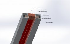
@Jonas Another great render! I get what you meant now, and i like your design very much! Especially using aluminium profile for holding magnets and iron, looks much nicer.
According to my calculator, you can't get 4 ohms using 2 wide strips of 4um alu, but at least you can get bigger resistance and efficiency.
As your ribbon looks pretty similar to mine, i am very interested in this new membrane you are making, so please keep us informed. I am only questioning the strenght of 4um alu on 2um mylar, can it hold ribbon membrane corrugated.
@Bolserst Having to turn off hvac really describes how gentle membrane is 🙂 But you really got great results.
I was already thinking about UMIK1, because, as you also said, it doesn't require external amps that add noise and complications, or analog cables. Glad that you found it has good calibrations in comparison to other measurement mics. Have to just buy it i guess, been using uncalibrated one for much too long. Thanks!
A picture tells more than words....!
verry nice render!!!. and nice design as well!. looking awesome.
Btw the curent returnpath is used for going back up then again down the second ribbon ? and then to the other pole of the amplifier?
i as well really like you design with the alumnium profiel verry classy way to create a verry long ribbon. and easy to make as well putting in the magnets with the metal strip is easy without things flying around. love it!
Thanks guys, for nice comments!
"Btw the curent returnpath is used for going back up then again down the second ribbon ? and then to the other pole of the amplifier?"
Yes!
"Btw the curent returnpath is used for going back up then again down the second ribbon ? and then to the other pole of the amplifier?"
Yes!
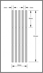
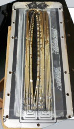
Magnet dimensions are 50mm x 5mm x 1.5mm....could you provide some dimensions from the original Neo 8s
- magnet dimensions
- magnet spacing
- magnet-to-diaphragm spacing
- conductor thickness
- conductor width.
Magnet-to-diaphragm spacing is 1.5mm, however some of that is taken up by a layer of damping felt.
Conductor width is estimated at 1.6mm for the vertical runs, based on measuring image.
Mass of the diaphragm + conductor combination was 0.43grams for the 1.5” x 6.25” section.
In ESL terms that would be equivalent to using a 52µm thick diaphragm.
Attachment #1: shows layout and spacing of magnets.
Attachment #2: shows magnets scaled and located horizontally where I believe they were relative to the conductors. Notice the larger gap between traces at the center-line of each magnet.
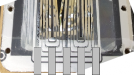
Attachment #3: larger image you might find useful for calculating an estimate of conductor thicknesses.
Hmmmm...now that I think about it, if I still have the outer shell pieces laying around they may have enough of the conductor remnants stuck to the border where they run around the output connections that I could measure the thickness.
Attachments
Last edited:
Magnet dimensions are 50mm x 5mm x 1.5mm.
Magnet-to-diaphragm spacing is 1.5mm, however some of that is taken up by a layer of damping felt.
Conductor width is estimated at 1.6mm for the vertical runs, based on measuring image.
Mass of the diaphragm + conductor combination was 0.43grams for the 1.5” x 6.25” section.
In ESL terms that would be equivalent to using a 52µm thick diaphragm.
Attachment #1: shows layout and spacing of magnets.
Attachment #2: shows magnets scaled and located horizontally where I believe they were relative to the conductors. Notice the larger gap between traces at the center-line of each magnet.
Attachment #3: larger image you might find useful for calculating an estimate of conductor thicknesses.
Hmmmm...now that I think about it, if I still have the outer shell pieces laying around they may have enough of the conductor remnants stuck to the border where they run around the output connections that I could measure the thickness.
ooh wow. funny how something so well regarded is so simple, and dont mind me saying cheap 🙂 magnets are dirt cheap in these sizes 🙂
Thank you or this information, now that these are no longer available I guess we'll have to build them ourselves.😀Magnet dimensions are 50mm x 5mm x 1.5mm.
Magnet-to-diaphragm spacing is 1.5mm, however some of that is taken up by a layer of damping felt.
Conductor width is estimated at 1.6mm for the vertical runs, based on measuring image.
Mass of the diaphragm + conductor combination was 0.43grams for the 1.5” x 6.25” section.
In ESL terms that would be equivalent to using a 52µm thick diaphragm.
Attachment #1: shows layout and spacing of magnets.
Attachment #2: shows magnets scaled and located horizontally where I believe they were relative to the conductors. Notice the larger gap between traces at the center-line of each magnet.
Attachment #3: larger image you might find useful for calculating an estimate of conductor thicknesses.
Hmmmm...now that I think about it, if I still have the outer shell pieces laying around they may have enough of the conductor remnants stuck to the border where they run around the output connections that I could measure the thickness.
From the Neo10 datasheet:

regards,
Gerrit
That reminds me...have any of you looked at the Neo10 patent before?From the Neo10 datasheet:
Figure 6 shows one interesting aspect of the design; using corrugation in the outer edges of the diaphragm to minimize diaphragm wrinkling and buzzing when the aluminum conductors get hot.
Attachments
Last edited:
That reminds me...have any of you looked at the Neo10 patent before?
Figure 6 shows one interesting aspect of the design; using corrugation in the outer edges of the diaphragm to minimize diaphragm wrinkling and buzzing when the aluminum conductors get hot.
Very interesting. Nice find!
A thousand thanks, Bolserst! You da man! That information will be very helpful as I try to do some reality checks on my choice of dimensions.
And let me add my voice to the chorus of praise for Jonas's design. Very elegant.
And let me add my voice to the chorus of praise for Jonas's design. Very elegant.
I had seen that Neo 10 spec sheet before and the drawing makes the magnets look much thicker than the ones Bolserst measured. The Neo 10 magnets look almost square in cross section in the drawing.
Bolserst's measurements, though, reveal the magnets in his driver are surprisingly (to me) thin. 1.5 mm?? I was getting worried that I was barking up the wrong tree with my 1/8" thick NdFeB magnets but perhaps not. That's welcome news because they're bought and paid for! Maybe the Neo 10 uses much thicker magnets to allow for a wider gap and longer excursion. Wasn't that part of their pitch for the Neo 10 model?
Again, very helpful information. Thanks for taking the trouble to provide it.
Few
I had seen that Neo 10 spec sheet before and the drawing makes the magnets look much thicker than the ones Bolserst measured. The Neo 10 magnets look almost square in cross section in the drawing.
Bolserst's measurements, though, reveal the magnets in his driver are surprisingly (to me) thin. 1.5 mm?? I was getting worried that I was barking up the wrong tree with my 1/8" thick NdFeB magnets but perhaps not. That's welcome news because they're bought and paid for! Maybe the Neo 10 uses much thicker magnets to allow for a wider gap and longer excursion. Wasn't that part of their pitch for the Neo 10 model?
Again, very helpful information. Thanks for taking the trouble to provide it.
Few
its mainly the size that increases the lower octaves. since it falls off under the resonance frequency fast.
i've seen neo 8 drawings with the same big magnets. although they use 1.5 mm magnets. making the thing wider decrease resoanance quickly. but also ads problems with directivitity.
bigger magnets increase overal spl though
I agree that the size of the diaphragm enables the driver to move more air and lowers the resonance frequency (all else being equal).
My recollection of the stated design goals for the Neo 10 included reasonably high SPL operation at lower frequencies, and they wanted to use longer excursion to help them do that. The perforated plates are curved so the diaphragm to magnet gap is largest near the middle of the diaphragm, where excursion is largest. That larger gap reduces the magnetic field strength so it would make sense to use larger magnets to help compensate for the larger gap. That's how I got to the point of wondering whether the Neo 10 uses thicker magnets, as shown in their drawing.
However, if the Neo 8 drawings also show thick magnets when in fact they're thin, then the artist's renditions are probably just consistently misleading. Clearly I trust Bolserst's measurements more than the sketches, and I'm happy to see thinner magnets can be made to work.
I was also interested to see how much overlap there is between the conductors and the magnets. The conductors aren't just positioned over the space between the magnets, they overlap the magnet edges a bit. I intended to do that as well so, again, I'm glad to see I may be on the right track.
Few
- Home
- Loudspeakers
- Planars & Exotics
- DIY ribbon dipole tweeter, reductio ad minimum