you can see in femm pretty easy how much overlap would be usefull. there is a sort of null point in the middle of the magnet when it switches from North to south. aah i wanna play to 🙂
Right, I agree. That's what motivated me to design in some overlap. It's just reassuring to me to see a developed commercial product designed with the same configuration.
You hadn't stated the goals for your planar, but if you want to use it as a tweeter as well as a midrange, you need to keep the magnets as thin as possible. All else being equal, the thicker the magnets are, the lower the frequency of the peak limiting high frequency extension. For example if the magnets in the neo8 were doubled in thickness, a simple lumped parameter acoustic model would predict that the peak would move from ~13kHz to around 9.2kHz....I'm happy to see thinner magnets can be made to work.
Some more test results. A 6µm ribbon with corrugation with just enough tension to flatten the ribbon in the gap, with a little more tension and essentially stretched out. Harmonics and spectral decay are shown:

I'm still not clear on what is causing the resonance. If it was a motion like in a guitar string one would expect the frequency to go up with tension, but the frequency goes down. I was thinking it could be a AMT like motion in the corrugation.
The increase of the third harmonic towards 1kHz is expected, the magnetic flux density is not constant but the deviation is symmetric so odd harmonics are to be expected as the excursion increases. A little more tension decreases the amplitude of the corrugation and thus the ribbon occupies a smaller area of the gap, this results in less distortion at 1kHz. The distortion increases for the stretched ribbon probably because there is to little freedom of movement for the ribbon.
The harmonics for the stretched ribbon with 24dB/oct LR high pass at 1.5kHz:

The high-pass filter significantly reduces the third harmonic and fifth, notice how the even harmonic are very much less affected by the filter.
More experiments to follow...
regards,
Gerrit
I'm still not clear on what is causing the resonance. If it was a motion like in a guitar string one would expect the frequency to go up with tension, but the frequency goes down. I was thinking it could be a AMT like motion in the corrugation.
The increase of the third harmonic towards 1kHz is expected, the magnetic flux density is not constant but the deviation is symmetric so odd harmonics are to be expected as the excursion increases. A little more tension decreases the amplitude of the corrugation and thus the ribbon occupies a smaller area of the gap, this results in less distortion at 1kHz. The distortion increases for the stretched ribbon probably because there is to little freedom of movement for the ribbon.
The harmonics for the stretched ribbon with 24dB/oct LR high pass at 1.5kHz:
The high-pass filter significantly reduces the third harmonic and fifth, notice how the even harmonic are very much less affected by the filter.
More experiments to follow...
regards,
Gerrit
A ribbon dipole tweeter reduced to the bare essentials that works and measures surprisingly well.
Is it necessary to divide the magnetic loudspeaker into 3 feq ranges indeed?
Are any technical/physical properties of the membrnes that tend us to make the 3 way magentostats?
"You hadn't stated the goals for your planar, but if you want to use it as a tweeter as well as a midrange, you need to keep the magnets as thin as possible. All else being equal, the thicker the magnets are, the lower the frequency of the peak limiting high frequency extension. For example if the magnets in the neo8 were doubled in thickness, a simple lumped parameter acoustic model would predict that the peak would move from ~13kHz to around 9.2kHz."
True. I wasn't very clear. I didn't want to hijack the thread.
I'm emphasizing the range from a few hundred Hz to maybe 3-7 KHz for the drivers I'm working on. I'll be using a vertical array of open baffle 8" woofers for the low end, and I'm leaving open the possibility of a ribbon or planar magnetic tweeter for the extreme highs. I'm too old to fret too much about 15-20 KHz so I haven't completely abandoned the idea of just equalizing the peak you referred to. I'll have to see if that's possible to an acceptable degree.
I am also starting with a single-ended (not push-pull) design. That will obviously reduce the sensitivity, and maybe the linearity, but it will also reduce the magnitude of the cavity resonance. I'll be aiming for a line source that's around 5' tall so I may be able to make up the sensitivity lost by using a one-sided magnet array by using lots of driver area.
Or maybe I'm just not thinking clearly...
Few
A ribbon dipole tweeter reduced to the bare essentials that works and measures surprisingly well.
Is it necessary to divide the magnetic loudspeaker into 3 feq ranges indeed?
Are any technical/physical properties of the membrnes that tend us to make the 3 way magentostats?
My goal was to create a real dipole in the horizontal plane and it is not possible to do that without using multiple drivers.
regards,
Gerrit
"You hadn't stated the goals for your planar, but if you want to use it as a tweeter as well as a midrange, you need to keep the magnets as thin as possible. All else being equal, the thicker the magnets are, the lower the frequency of the peak limiting high frequency extension. For example if the magnets in the neo8 were doubled in thickness, a simple lumped parameter acoustic model would predict that the peak would move from ~13kHz to around 9.2kHz."
True. I wasn't very clear. I didn't want to hijack the thread.
I'm emphasizing the range from a few hundred Hz to maybe 3-7 KHz for the drivers I'm working on. I'll be using a vertical array of open baffle 8" woofers for the low end, and I'm leaving open the possibility of a ribbon or planar magnetic tweeter for the extreme highs. I'm too old to fret too much about 15-20 KHz so I haven't completely abandoned the idea of just equalizing the peak you referred to. I'll have to see if that's possible to an acceptable degree.
I am also starting with a single-ended (not push-pull) design. That will obviously reduce the sensitivity, and maybe the linearity, but it will also reduce the magnitude of the cavity resonance. I'll be aiming for a line source that's around 5' tall so I may be able to make up the sensitivity lost by using a one-sided magnet array by using lots of driver area.
Or maybe I'm just not thinking clearly...
Few
As I understand it a push-pull design is essential to create a constant field. I suggest you do some modelling in FEMM to find out what the field looks like.
regards,
Gerrit
I have done some FEMM modeling of single-sided and push-pull magnet assemblies. Predictably, the push-pull system yields a symmetric magnetic field: the field on both sides of the diaphragm looks the same. But it's not like the situation with electrostatic fields where a push-pull arrangement guarantees a uniform electric field between the stators. The magnetic field of a push-pull system is symmetric but not necessarily uniform.
The single-sided magnet assembly doesn't have the symmetry of the push-pull arrangement but the uniformity of the field need not be too bad. Magneplanars have done pretty well with single-sided operation, for example. At least I've found that they sound quite good; I haven't done a careful survey of measurements of them.
I'm not aiming for extended low frequency response, and I intend to have quite a bit of diaphragm surface area. I'm therefore hoping that I can keep the excursion low enough so that the magnetic field the diaphragm feels is sufficiently uniform, even with a single-sided design. That would avoid some construction difficulties and reduce the severity of the resonance Bolserst mentioned.
Few
This really is puzzling behavior isn't it?...I'm still not clear on what is causing the resonance. If it was a motion like in a guitar string one would expect the frequency to go up with tension, but the frequency goes down.

Did you happen to look/listen while playing low level sine signal to see what the motion of the ribbon is when frequency is swept or held around the resonance frequencies?
This really is puzzling behavior isn't it?
Did you happen to look/listen while playing low level sine signal to see what the motion of the ribbon is when frequency is swept or held around the resonance frequencies?
Puzzling indeed. No I didn't look closely but that's a good idea. I ordered some mylar foil and are waiting for it to arrive, then I will do some more testing.
regards,
Gerrit
This really is puzzling behavior isn't it?
Did you happen to look/listen while playing low level sine signal to see what the motion of the ribbon is when frequency is swept or held around the resonance frequencies?
I don't know the cause of this behavior, but maybe you can think of it like this:
If the phenomena was due to a strings behavior, the resonance would go up in frequency with increased tension, we all agree.
In the case of a corrugated alu ribbon, we have a small spring action and the resonance point depends on the ribbons spring constant and tension.
The spring action of aluminium is very fragile, and when we increase the tension, the spring action behavior is destroyed, thus lowering the resonance frequency.....
If this reasoning is correct, it means that we shall not pull the ribbon at all, when mounting it...
Last edited:
Some more test results....
More experiments to follow...
regards,
Gerrit
Fantastic results as always! I always thought that i heard resonances of free hanging corrugated ribbons, and as you said, the problem is probably due to very different movement of ribbon. We have huge area of ribbon at almost 45 degrees from the normal plane where ribbon should be, and it moves in vry strange behaviour. Practically, every dip or peak is holding two other sides of ribbon that are moving towards or away from each other. As Jonas said, there is also some spring effect added to that.
Did you try embossed straight ribbon in the same magnetic field, just for the fun of it?
Best regards,
Mihailo
I don't know the cause of this behavior, but maybe you can think of it like this:
If the phenomena was due to a strings behavior, the resonance would go up in frequency with increased tension, we all agree.
In the case of a corrugated alu ribbon, we have a small spring action and the resonance point depends on the ribbons spring constant and tension.
The spring action of aluminium is very fragile, and when we increase the tension, the spring action behavior is destroyed, thus lowering the resonance frequency.....
When the ribbon is stretched a little it is still elastic and will bounce back so to speak but the resonance frequency drops. The stretched out ribbon is indeed no longer elastic.
Fantastic results as always! I always thought that i heard resonances of free hanging corrugated ribbons, and as you said, the problem is probably due to very different movement of ribbon. We have huge area of ribbon at almost 45 degrees from the normal plane where ribbon should be, and it moves in vry strange behaviour. Practically, every dip or peak is holding two other sides of ribbon that are moving towards or away from each other. As Jonas said, there is also some spring effect added to that.
Did you try embossed straight ribbon in the same magnetic field, just for the fun of it?
Best regards,
Mihailo
Thank you 🙂
Flat ribbons do not have resonance issues but the distortion is intolerable. I also tried the embossing method bolserst used but there was still to much distortion. I also tried embossed ribbons with 1cm corrugation at the ends, didn't help either. The best result so far was with a 4.6µm ribbon with a thin shellac coating on one side:

Not that much resonance with a 3rd harmonic peak of 0.9%. The spectral decay is also pretty clean:

The resonance is not very pronounced but because it is in the range where our hearing is very sensitive I would like to get rid of it completely. I'm anxious to try Jonas' method with the mylar, I ordered 2µm and 1µm mylar so I can try different combinations of ribbon thickness and mylar. The goal is to come up with a simple recipe that gives repeatable results.
regards,
Gerrit
Thank you 🙂
Flat ribbons do not have resonance issues but the distortion is intolerable. I also tried the embossing method bolserst used but there was still to much distortion. I also tried embossed ribbons with 1cm corrugation at the ends, didn't help either. The best result so far was with a 4.6µm ribbon with a thin shellac coating on one side:
Not that much resonance with a 3rd harmonic peak of 0.9%. The spectral decay is also pretty clean
The resonance is not very pronounced but because it is in the range where our hearing is very sensitive I would like to get rid of it completely. I'm anxious to try Jonas' method with the mylar, I ordered 2µm and 1µm mylar so I can try different combinations of ribbon thickness and mylar. The goal is to come up with a simple recipe that gives repeatable results.
regards,
Gerrit
Thanks man, those results are very interesting. That means that we must choose between resonances and distortion. That coated ribbon looks very promising, very nice results! I am very interested in mylar/alu results as i am planning on replacing my quasi ribbon membranes in near future, so please post your findings. And can you please tell us where you ordered that thin mylar? (i still source mine from mkp capacitors but it's thicker than that).
As i told Jonas earlier, with mylar you have option to make strips and make huge gain in sensitivity if you want, and thats another big bonus. It's just that they don't offer that much high freq. resolution (probably speed because of heavier membrane) of pure alu ribbon. Glue also adds weight.
Best of luck with further experiments, we all like it!
Mihailo
I ordered the mylar at Free flight supplies, look for 'LW Covering' The order was placed tuesday, with a bit of luck the foil will be here soon.
The shellac was 'politour' used for furniture, a shellac in alcohol solution.
I will post new results as soon as there's something worthwhile to post.
regards,
Gerrit
The shellac was 'politour' used for furniture, a shellac in alcohol solution.
I will post new results as soon as there's something worthwhile to post.
regards,
Gerrit
Last edited:
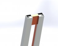
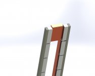
Sitting here thinking, on how to integrate a drive transformer in my alu tube ribbons..tell me if I'm hijacking.
What, a drive transformer?😕
Well, it has some positive sides to it, the ribbon becomes very easy to drive (SE tube Amp), smaller value of crossover caps and some other things, like making a transformer (which is very fun.....)
The pictures shows the speaker without a ribbon mounted for making things clearer.
The ribbon itself is used as a transformer winding(!), so one mylar backed ribbon end is attached to the lower copperplate and wound 4 (in my case) times around the transformer core/contact area.
The other end is attached (without pulling) over the upper copper contact, and a metal clip holds it in place.
The lower winding has (in my case) 80 turns which means that the resulting impedance becomes (80/4)x(80/4) times ribbon resistance = 40 Ohm...
Attachments
Sitting here thinking, on how to integrate a drive transformer in my alu tube ribbons..tell me if I'm hijacking.
What, a drive transformer?😕
Well, it has some positive sides to it, the ribbon becomes very easy to drive (SE tube Amp), smaller value of crossover caps and some other things, like making a transformer (which is very fun.....)
The pictures shows the speaker without a ribbon mounted for making things clearer.
The ribbon itself is used as a transformer winding(!), so one mylar backed ribbon end is attached to the lower copperplate and wound 4 (in my case) times around the transformer core/contact area.
The other end is attached (without pulling) over the upper copper contact, and a metal clip holds it in place.
The lower winding has (in my case) 80 turns which means that the resulting impedance becomes (80/4)x(80/4) times ribbon resistance = 40 Ohm...
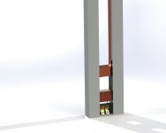
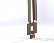
The steel frame ribbon will be driven with a transformer, the NCore with the series resistor is for testing. I fooled around building a transformer myself until somebody showed me how it's done (thank you again for that Peter).

The primary inductance is 62mH and the leakage inductance is just under 4µH yielding a coupling factor of 0.99994. This is achieved by a perfect interleaving of primary (single 66 turns) and secondary ( 11 x 6 turns) windings.
The design in your sketch will not have a sufficiently low leakage inductance which will affect the high frequency response. The inductance in the secondary circuit has to be very low. In the picture the copper foil is separated by thin polyester foil, increasing the distance between the copper foils by just 1mm decreases the high frequency roll-off by 30%!.
Another issue when using a transformer is that the contact resistance has to be very constant, especially when using a tube amp, because changes in the secondary circuit resistance will be reflected to the primary.
My surround speakers use a Hypex AS2.100 plate amp and in this case a transformer is required, this might change in the future but for now it works very fine this way.
regards,
Gerrit
I ordered the mylar at Free flight supplies, look for 'LW Covering' The order was placed tuesday, with a bit of luck the foil will be here soon.
The shellac was 'politour' used for furniture, a shellac in alcohol solution.
I will post new results as soon as there's something worthwhile to post.
regards,
Gerrit
Thanks buddy! Prices are mad - very cheap, i will order for sure from them when i get time to rebuild ribbons. As i will probably go with 6um alu, i need much thinner mylar behind it, so that aluminium can corrugate both itself and mylar. Otherwise it will stretch over time.
That shellac experiment has me scratching head, but i guess it is proven by now in your measurements. Only thing that we don't know is how long can it stay on aluminium.
Looking forward for your next measurements, as they are always very informative!
ooooOOOOoooh! This makes perfect sense.…In the case of a corrugated alu ribbon, we have a small spring action and the resonance point depends on the ribbons spring constant and tension. The spring action of aluminium is very fragile, and when we increase the tension, the spring action behavior is destroyed, thus lowering the resonance frequency...

Basically trying to add tension reduces the spring constant of the fragile aluminum corrugated spring.
With mass and airload remaining the same, if you reduce the spring constant:
- resonance frequency will go down
- damping ratio will go up (ie Q of resonance reduced)
This is exactly what the measurements show.
- Home
- Loudspeakers
- Planars & Exotics
- DIY ribbon dipole tweeter, reductio ad minimum