Bolserst: My midrange conductors are in series-parallel. Each conductor is about 4 ohms individually and I first created pairs in series to get up to 8 ohms and then paralleled the pairs to get back down to 4 ohms. I'd rather retain the sensitivity in any case. I have the necessary amplifier channels to run the tweeter separately, so it's not a huge problem. I did like the sense of simplification going down to just one four-channel amp would provide, but for now I guess I'll stick with the flexibility separate dsp control of each range (woofer, midrange, tweeter) brings.
I'd lost track of the graphics in post 181 so thanks for the reminder. That blooming sure looks familiar! You're no doubt right about the undriven diaphragm and the baffle width working against ideal dipole behavior. I made those decisions knowing they were a bit of a compromise. Now that I have some measurements on the system I'm still fine with the choices I ended up making because they allowed me to meet other design goals.
I made some 40 degrees off axis measurements this morning with a variety of crossover frequencies (500-5000 Hz in 500 Hz increments), with both 2nd order Bessel and first order filters. I'm still fussing around with the analysis so I'm not ready to draw any conclusions or post anything yet. Plus, I'm leaving town tomorrow for the rest of the week, and just shipped off my four-channel amp for repairs, so I'll be out commission for awhile.🙁
Few
Mark: I'll have to wait until my amp returns before I can pick up the testing. I haven't yet looked at impedance so I should get around to that. What, in particular, are you hoping to see in the impedance plot? Given the planar magnetic design, I'm expecting to see the fundamental resonance down in the tens of Hz range, and not a ton more, unless there are wiggles from some diaphragm or frame resonances. Is there something else you had in mind?
Few
Few
Wouldn't hurt to try. See what you get. Impedance can present a lot of info.
If it's clean, you would have verified that part. One less thing to worry about.
A simple procedure with more information to gain. 🙂
While you're at it, do the woofer towers too!
If it's clean, you would have verified that part. One less thing to worry about.
A simple procedure with more information to gain. 🙂
While you're at it, do the woofer towers too!
I agree, and I'll do the measurement when I'm back up and running. I meant to ask if Mark was suggesting that I look for something beyond the items I listed.
Few
Few
My impression (based on an awful lot of FR curves) is that real-world indoors dipole responses bear little signature of the familiar textbook or Linkwitz model. Easy to take a piece of paper and draw rays front and back in anechoic space. But quite a different picture when the rays are bouncing around.To approach an ideal dipole response....
Can you think of any trustworthy evidence about dipole performance in rooms?
Ben
Last edited:
Mark: I'll have to wait until my amp returns before I can pick up the testing. I haven't yet looked at impedance so I should get around to that. What, in particular, are you hoping to see in the impedance plot? Given the planar magnetic design, I'm expecting to see the fundamental resonance down in the tens of Hz range, and not a ton more, unless there are wiggles from some diaphragm or frame resonances. Is there something else you had in mind?
Few
WHen you have the three measurement son the same graph laid out correctly you can make inferences on what is happening mechanically to cause purterbations in the frequency domain. A phase wiggle at exactly the same point as a impedance wiggle or a frequency wiggle shows relationship. A phase lag shows stored energy or possibly a reflection.
I can tell you a decent bit of information from carefully done measurements like this.
Much more than the graphs you have presented so far.
Nothing on it's own tells a person the entire gamut of what is happening in the sound from a loudspeaker. But like a house, you start with the basics, the foundation and you build up from there.
Trying to put the shingles on first can be a little tricky 😉
And all the time domain information you are posting is not useless. But you are looking in the hardest possible place to find some answers as to what is happening.
If you start with the simpler things the more complex start to fall into place.
Remember the simple distance calculation I gave you to look for the unwanted reflections in the planars. I have never really sean a complete picture of your speakers. Yet from the measurements I could suggest the areas that were causing you the problems. Simply applied experience. I think I learn the most from fixing my mistakes. And I have to say the more I investigate this field of endeavour the less I really understand. But I'm enjoying the ride! And I learn new things every day. That keeps me interested in continuing the ride.
Joseph D'Apolito's book gives great insight into how the measurements can be interpreted.
How about all the lovely data Few has posted, or some of the data from other dipole projects that have been linked to?My impression (based on an awful lot of FR curves) is that real-world indoors dipole responses bear little signature of the familiar textbook or Linkwitz model. [Easy to take a piece of paper and draw rays front and back in anechoic space. But quite a different picture when the rays are bouncing around.
Can you think of any trustworthy evidence about dipole performance in rooms?
Can you share some of the FR curves that serve as a basis for your impression?
I fear this will be another case similar to the excessive directivity of large flat ESLs where no amount of measurement data will sway you from your opinion. But, the question you didn’t ask (but maybe meant to) is actually a good one.
"Why do people think that an ideal dipole radiation pattern is desirable?"
Being an avid ready of Toole, you are aware that having uniform or smoothly trending frequency response that decreases in level as you move off-axis results in high listener satisfaction. This is exactly what an ideal dipole radiation pattern is. The result is that the ratio of direct sound to room sound is increased, and what room sound there is has a spectral balance that matches that of the direct sound to a substantial degree. You will find that MMM measurements and windowed first arrival measurements would differ less than without an ideal dipole radiation pattern. Said another way, the speaker becomes less room dependent.
The caveat that goes with the above is that we are talking above the Schroeder frequency. Room modes will still dominate the LF response, and dipoles will just act like spaced monopoles driving the room.http://www.diyaudio.com/forums/multi-way/121590-cardioid-bass-26.html#post1508846
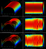
Just for fun, attached is a plot comparing ideal dipole response and the polar response of Few’s planar towers. The bottom set of plots includes considerable room energy in the 50mS window and yet the dipole nature is still easily discernible, although you can start to see room modes taking over below 300Hz in the sonogram view.
Attachments
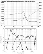
Have you been able to see impedance variations from reflections or other acoustic problems with planar drivers? I haven’t had much luck with it. Unlike dynamic drivers, the coupling between the acoustic/mechanical domain and the electrical domain is pretty weak. As an example, even diaphragm resonance with a 10-15dB peak results in barely perceptible wrinkle in Magnepan impedance.WHen you have the three measurement son the same graph laid out correctly you can make inferences on what is happening mechanically to cause purterbations in the frequency domain. A phase wiggle at exactly the same point as a impedance wiggle or a frequency wiggle shows relationship…
Magnepan Magneplanar MG3.6/R loudspeaker Measurements | Stereophile.com
Magnepan Magneplanar MG1.6/QR loudspeaker Measurements | Stereophile.com
+1Joseph D'Apolito's book gives great insight into how the measurements can be interpreted.
Attachments
Once again, many thanks for a thorough and clear big-picture on the musical charms of dipoles. But you give me undeserved credit for thinking I knew how to ask a better question than I knew to ask.How about all the lovely data Few has posted, or some of the data from other dipole projects that have been linked to?
Can you share some of the FR curves that serve as a basis for your impression?
...
The caveat that goes with the above is that we are talking above the Schroeder frequency. Room modes will still dominate the LF response, and dipoles will just act like spaced monopoles driving the room.
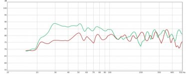
First, you've answered my initial little question with "above the Schroeder frequency...". You seem to agree that my point of view (which I should have made more evident) related to Linkwitz and low freq phase cancellation. And as you asked, below I've posted a comparison of a small sealed box sub on one side of the room with a giant OB sub on a different wall, 1/12 smoothing. The green curve - the one with the great low bass - is the OB.
Despite the difference of "suspension", below 100 Hz the two subs are notably similar. While in the region 100 to maybe 180 or 200 where the subs are playing, they are not. In other words and as you say, the low freq sound at my chair depends a lot on the room and less on the theory of OB phase cancellation. There may have been a bit of EQ applied in these curves (can't remember), but any EQ might have reduced the similarity of the curves.
Second, about the satisfying theoretical purity of Few's curves, as far as I understand his measurement set-up and room, there is less "room" in his measurements and more "speaker". I'm glad to see acoustic theory sustained, even if you chide me for the "disruptive" instincts we now see rising in our culture.
Ben
Attachments
Last edited:
Have you been able to see impedance variations from reflections or other acoustic problems with planar drivers? I haven’t had much luck with it. Unlike dynamic drivers, the coupling between the acoustic/mechanical domain and the electrical domain is pretty weak. As an example, even diaphragm resonance with a 10-15dB peak results in barely perceptible wrinkle in Magnepan impedance.
Magnepan Magneplanar MG3.6/R loudspeaker Measurements | Stereophile.com
Magnepan Magneplanar MG1.6/QR loudspeaker Measurements | Stereophile.com
+1
You have presented a difficult question to answer and an impossible to use source of i formation.
In my work I use a Smith &Larson SpeakerTesterPro. It can be used to resolve very small impedance fluctuations. Whereas the information you use in the Stereophile graph is there as a statement. But a statement that I can neither verify not use as an example.
As a simple point. Resonance on a planar is hard to find. And it will be at the impedance maximum and the phase 0 crossing point. A dual parameter measurement is required for that. But a very high resolution measurement to be able to discern it. As you say correctly that the impedance bump is very small.
I think I mentioned at some point that measuring these types of drivers is jumping into the deep end of the pool 😀
Hi,
jauu
Calvin
Just walk around a Dipole -regardless of subwoofer or panel- and You can hear the Dipole-8 distribution.Can you think of any trustworthy evidence about dipole performance in rooms?
jauu
Calvin
What particular failure of judgment, taste, or good standards on my part are you urging the forum to recognize?Ben.
Don't you listen to esl's?
(Kidding of course. I greatly respect neighbour Mark and welcome his constructive criticism of any foolish thing I might have posted.)
Ben
PS Yes, "full range" curved ESL panels, about 120 Hz up to dog-whistle, made from 6 Dayton-Wright cells each side; I built them around 1978 and returned to service recently after 30 yr hiatus, 10kV home-brew bias supply, no gas bag
Last edited:
Sorry, it wasn’t supposed to be a difficult question…just a simple yes or no if you had had any luck troubleshooting planar response anomalies with impedance measurements. I was curious, since I have not. It sounded like Few planned to perform some impedance measurements when he gets his amp back, so we will see what if anything can be gleaned from them.You have presented a difficult question to answer…
aaAaah…ok. Considering all discussion and measurements in this thread have thus far been geared to the planar midrange/tweeter towers I jumped to the conclusion that your statement was related.…my point of view (which I should have made more evident) related to Linkwitz and low freq phase cancellation.
While I agree that room modal response is a large contributor to LF response when the listener is placed across the room from a LF source, it is pretty difficult to draw any conclusions from a single measurement with your two sources placed in different locations. Not sure how close your OB sub was to the wall, but that has a huge effect on its radiation pattern as well.And as you asked, below I've posted a comparison of a small sealed box sub on one side of the room with a giant OB sub on a different wall, 1/12 smoothing. The green curve - the one with the great low bass - is the OB.
If curious, you might try placing each woofer out toward the middle of the room, play some LF noise and walk around it as Calvin suggested. You will find when close to the woofer the radiation pattern of the source will be evident(monopole or dipole). As you increase distance from the source as you walk around you will find (for the most part) they will start sounding more similar as the room modes start to dominate the sound reaching your ears. I said “for the most part” because it is possible for particular rooms with particular dipole source and listener placement to have one or more room modes different in level compared to a monopole source. But, research in room acoustics has shown that to be more of a special case than a general rule.
Sorry, it wasn’t supposed to be a difficult question…just a simple yes or no if you had had any luck troubleshooting planar response anomalies with impedance measurements. I was curious, since I have not. It sounded like Few planned to perform some impedance measurements when he gets his amp back, so we will see what if anything can be gleaned from them.
I don't know how small an impedance variation he can resolve using REW. That is why it is a difficult question.
What I can do here at my place is probably a little different than what Few can accomplish without dedicated equipment.
But there should be enough correlation between the three different measurements of phase frequency and impedance to give us a bit of information.
Mark: I believe you mentioned your SpeakerTesterPro system measures two parameters. Does it use phase sensitive detection like a lock-in amplifier? I have one of those in my research lab but without a pressing question to answer I'm reluctant to rip it out of that system and haul it home to use it for speaker testing. I'm guessing that I could pick out smaller impedance ripples that way but I'm not really looking for another project, which is what would likely be involved. Nonetheless, I'm curious about the measurement tricks your system employs.
Few
P.S. My ailing amplifier made it to California today so maybe I'll be back in action this week or early next week.
Few
P.S. My ailing amplifier made it to California today so maybe I'll be back in action this week or early next week.
Mark: I believe you mentioned your SpeakerTesterPro system measures two parameters. Does it use phase sensitive detection like a lock-in amplifier? I have one of those in my research lab but without a pressing question to answer I'm reluctant to rip it out of that system and haul it home to use it for speaker testing. I'm guessing that I could pick out smaller impedance ripples that way but I'm not really looking for another project, which is what would likely be involved. Nonetheless, I'm curious about the measurement tricks your system employs.
Few
P.S. My ailing amplifier made it to California today so maybe I'll be back in action this week or early next week.
It's actually three different measurements that are best suited to telling you the greatest amount of information. Frequency response phase response and impedance. The normal way of displaying this information is on a three in one graph that all share in common.
I can check what the impedance resolution of REW is. I believe it will be linked to the ADC in your computers sound card. Since almost all of them are 24 bit now you should be able to resolve pretty tiny impedance fluctuations.
But that is linked to what is written and made possible in the REW program.
And I will have to check that out.
You need not remove a special piece of equipment to do this type of a test. Your existing REW program with the appropriate voltage divider setup will work well enough.
Look in the REW manual. It's all there.
When referring to multiple parameters, I was referring just to the impedance part of the measurement, not the acoustic response.
I did look at the REW manual, which is why I started thinking about ways that more sophisticated systems might make an impedance measurement. My "soundcard" is an old M-audio M-track which maxes out at 48 KHz. I'm not sure how many bits it resolves but I think it's 16 rather than 24. So, given the weak link between the acoustic and electrical aspects of a planar magnetic speaker (as described by Bolserst), and the limited resolution of my audio interface, I'm not optimistic about unearthing new details with an impedance measurement made with my current system. If I can make the measurement without risking damaging my audio interface (ref. REW manual) I'll give it a try and report back once my amp is back in hand.
Few
- Home
- Loudspeakers
- Planars & Exotics
- DIY planar magnetic + open baffle woofer array