16 bit will be able to resolve in milliohms quite easily.
Not so long ago 8 bit oscilloscopes were pretty acceptable.
Not so long ago 8 bit oscilloscopes were pretty acceptable.
So a little fooling around with a sample data set from REW

REW will let you zoom in to the division of 0.1 ohms. And then allow a further expansion of the data in terms of the physical distance between the vertical lines.
Pretty nice really.
You should be able to see the small impedance peak in your planars. And possibly any impedance variations present in measurement.
Got it. Thanks. I know some of my diaphragms could use re-tensioning and that may show up in an impedance plot. I'm not ready to take things apart to play with the tension, though, especially since I'm not aware of problems while listening.
On the other hand, at some point I may make a pair of planar magnetic panels to straddle a computer monitor. I can imagine the impedance plot being quite useful if I decide to compare panels with and without my stretch-wrap "surrounds".
Few
On the other hand, at some point I may make a pair of planar magnetic panels to straddle a computer monitor. I can imagine the impedance plot being quite useful if I decide to compare panels with and without my stretch-wrap "surrounds".
Few
http://img.canuckaudiomart.com/uplo...on-mm702-planar-magnetic-desktop-speakers.jpg
Used to be able to buy these a few years back.
Perhaps I could do something about it?

😉
Used to be able to buy these a few years back.
Perhaps I could do something about it?
😉
Why not?!
I was pretty impressed by what a single one of my panels could do when I was testing them individually before installation. I'd need a convenient way to equalize it but for nearfield listening I could probably run the thing full range---no woofers. Plus I'm confident I could come up with a FAR simpler design and assembly approach now that I have some experience under my belt.
Few
Well the motor return plate in my hand was laser cut out of 1008 steel.
Not that hard to do even with a scroll saw and steel blades.
If you tape two together at the same time you can do a front and back at the same time for push pull operation.
This size is a bit small for a wide band. I have listened to it. It works decently to about 120 hertz. Like the Monsoon system it is best with a small subwoofer.
Looks pretty nice! I went single-sided rather than push-pull and, as an amateur, I'm glad I did. I wanted a bit more diaphragm area without the pleasure of trying to deal with the forces from opposing magnets. I'll leave that to you pros.
Few
Few
Well the construction is not that difficult. And you gain in distortion reduction.
But if I remember correctly you have pretty stellar distortion numbers in the first place.
But if I remember correctly you have pretty stellar distortion numbers in the first place.
For best resolution you will want to use a sense resistor that is similar in resistance to the planars being measured, and adjust gains to use as much of the ADC range as possible.I did look at the REW manual, which is why I started thinking about ways that more sophisticated systems might make an impedance measurement. My "soundcard" is an old M-audio M-track which maxes out at 48 KHz. I'm not sure how many bits it resolves but I think it's 16
It seems I am still failing to communicate the question properly….I was not asking about REW or about Few’s planars. I was asking about your experience with your planar projects and your measuring equipment. I was curious if you had had success diagnosing anomalies in your planar frequency response with impedance measurements.I don't know how small an impedance variation he can resolve using REW. That is why it is a difficult question.
For best resolution you will want to use a sense resistor that is similar in resistance to the planars being measured, and adjust gains to use as much of the ADC range as possible.

It seems I am still failing to communicate the question properly….I was not asking about REW or about Few’s planars. I was asking about your experience with your planar projects and your measuring equipment. I was curious if you had had success diagnosing anomalies in your planar frequency response with impedance measurements.
Or maybe I'm a little thick today?
Planars are difficult. But with phase frequency and impedance really zoomed in you can find correlations in what is going on.
You end up looking first at the frequency response. When there is a ripple or more to the point a dip you will usually be able to find a mechanical reason. That should show up as an impedance variation or at the very least a phase variation.
Doing this kind of sleuthing gets you information into the possible reflections and mechanical tension problems. Depending on drive level you may even find some problems in the distance between the motor and the diaphragm.
In Matt's case we have a finished system. And there is much more information that can be had.
There were reflections that he was chasing a few weeks ago. And there may still be some causing response anomalies.
@ FEW
You killed your amp?
For sure, a trustworthy method.For best resolution you will want to use a sense resistor that is similar in resistance to the planars being measured, and adjust gains to use as much of the ADC range as possible.
But, as a skeptical empiricist, I work differently. I do the impedance testing set-up but where the speaker would be, I stick a known resistor, say 10 Ohms, about the size of the speaker, and do a trace. Then I do a trace with a 17 Ohm resistor and then a 38.5 Ohm resistor.
Looking at an REW overlay chart, you can see horizontal lines - more or less flat - representing each of those resistances. Then you run the speaker and see where it falls.
That kind of procedure reveals any weird feature of your testing set-up (or error on your part) and I find it a trustworthy way to work.
B.
No I didn't kill my amp, thankfully. It's a new purchase---a four-channel class d amp puts out ~600 watts/channel into 4 ohm loads---and it works great except that one channel has a squeal when the amp is powered down. The manufacturer has been super-responsive and is confident that it's a power supply hiccup that he's run into in a few rare cases before. So, as long as all goes as expected, I should be back in action before too long. It's really driving me crazy not being able to play the speakers!
Thanks, all, for the set-up advice for the impedance measurement. Have most folks been using a power amp to make the measurements? If so, have you inserted a voltage divider and zeners to protect your soundcard?
Few
Thanks, all, for the set-up advice for the impedance measurement. Have most folks been using a power amp to make the measurements? If so, have you inserted a voltage divider and zeners to protect your soundcard?
Few
Well There are a couple of ways to look at the electrical tests. The original idea behind the Thiele Small testing was low levels. That would not require an amplifier.
I can test at low level and at high power.
And the tests do not come out the same.
The math is worked out for calculation of the the data provided by the low power testing.
You decide what you think will work out best.
If you want my opinion I'd say go with the low power as in from the soundcard testing method.
Have most folks been using a power amp to make the measurements? If so, have you inserted a voltage divider and zeners to protect your soundcard?
As far as I know sound card amps, as long as the load seen by the sound card or the amp is high enough there's no problem. With impedance measurements, you need a large resistor in series with the speaker under test.
The challenge may be in ensuring your wiring is correct (that is, ground goes to ground).
One more reason to use my procedure that "tests" resistors and provides the calibration. That way you see if you are getting nice flat lines and you can even eyeball the distortion in those resistors (which tells you how much distortion is present in the loop).
BTW, with the test system I outlined earlier, you don't need a super-large series resistor because you are seeing the calibration whatever the resistor. That eases requirements for voltage output in order to get a readable signal.
B.
Thanks for the responses. I want to be sure I understand "the soundcard method" because it's not one I saw in the REW manual. Does it involve driving the speaker directly with the soundcard output? The REW manual suggests either an headphone output or an amp output with a bunch of zeners and voltage dividers to prevent frying the card.
Few
Few
The interface between the soundcard is indeed through the headphone output.
If I remember correctly you are advised to use a decently high value resistor.
I'll send you some information. It's a little complicated to send it via the forum.
If I remember correctly you are advised to use a decently high value resistor.
I'll send you some information. It's a little complicated to send it via the forum.

One way that works.
The resistor is 100 ohms as this is a realistic load for a conventionally designed headphone amplifier.
The principal of operation is a voltage divider. So a little higher value resistor will work as well.
A metal film resistor is best. If you have something more exotic great. But the principal in choosing a resistor is to keep it noninductive. So a wire wound would be a poor choice.
Last edited:
Well I'm expecting my repaired amp to be back in service in the next two days so that'll put me back in action. I have on order some adapters so I can get at the signals I need in order to do the impedance tests. I'm hoping those will arrive in the next few days as well.
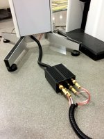
I finally finished cleaning up the wiring to the speakers. I didn't have a convenient baffle to mount connectors onto so I bought some Penn aluminum boxes from Parts Express. I could have done something a little simpler but back when I purchased them I wanted to keep open the possibility that I'd incorporate some passive crossover components. The boxes would let me do that without creating a mess. I need to tweak the cable lengths to neaten up the final product but I want to finish a cabinet that will hold my amplifiers and other electronics first in case that necessitates more cable adjustments.
Today's frustration was that I downloaded a demo version of Arta software to try out for speaker testing. It's PC-only, which I knew, but what I lost track of is the fact that my audio system, as it stands at the moment, accepts only digital inputs. The only PC I have at home is a Surface Pro 3 which only has one usb port and a displayport. There's no TOSLINK included in the headphone jack as there is in the Macbook Pro I've been using for my measurements so far.
I need one usb port for the interface with my M-Audio M-Track soundcard so I thought I'd look into a usb hub and a usb-to-TOSLINK (or to-S/PDIF) converter for the digital output. After far more searching than I expected I think I identified a collection of devices that would make all the connections but what a mess it would introduce! Plus, I don't know whether the usb hub would introduce any glitches into the synchronization of the audio input and output. So it seems I would need to shell out a bunch of money to buy hubs and converters just to try out the "free" demo version of Arta. If someone out there has a smarter approach to suggest please let me know. I could probably buy a newer audio interface with the connections I need by the time I'm done loading up on adapters.
Few
Attachments
- Home
- Loudspeakers
- Planars & Exotics
- DIY planar magnetic + open baffle woofer array