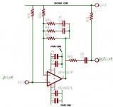
maxw said:I am working on a new layout simlar to RJM's above one and I am wondering can I separate the signal and power grounds like this??
Also, the ground cable that comes from yout TT, is that just chassis/power ground?
So if my power/chassis and signal grounds were seperate I would still connect that lead to the case of my pre-amp right?
can I separate the signal and power grounds like this??
No, you have to connect the power gounds to the signal grounds somewhere, preferably between R2 and R7.
The TT ground connects to the chassis, which is ideally connected to the circuit ground at the point where the signal and power grounds meet.
-R
Just finish my VSPS. It sounds good and is very quiet. In order for me to hear, any noise I must turn the volume all the way than be within 12" of the speakers. All the parts came from an old Apple computer and a dead UPS,so it cost $00.00.
By the way, if you see any old apple computers and if it cost a $1 or two buy it. The parts are worth it.
AC input filter
Poly caps
Elec caps from 16 to 400volts(use only if computer works)
Heatsink
small inductors
resistor from .5 to 3 watts
and more.
By the way, if you see any old apple computers and if it cost a $1 or two buy it. The parts are worth it.
AC input filter
Poly caps
Elec caps from 16 to 400volts(use only if computer works)
Heatsink
small inductors
resistor from .5 to 3 watts
and more.
Did you happen to take some pictures, you want to share?Just finish my VSPS.
Steen🙂
R2 confusion
I'm working on my VSPS, and I'm confused about the location of R2. On the schematic it seems to connects between the Opamp's (-) input and the ground, while in the layout diagram it is not in the same place; it's between the opamp's output and ground.
I assume.. as long as I'm not making a mistake myself, that the schematic is correct?
Hm.. maybe i'm confused, but I did some more examining of the schematic and the layout.. It looks to me like C2 and R4 switched position going from the schematic to the layout, as did C1 and R3..
I'm looking at this: http://www.geocities.com/rjm003.geo/rjmaudio/images/vsps.gif
and this:
http://www.geocities.com/rjm003.geo/rjmaudio/images/vsps_layout.gif
thanks for the help!
I'm looking at this: http://www.geocities.com/rjm003.geo/rjmaudio/images/vsps.gif
and this:
http://www.geocities.com/rjm003.geo/rjmaudio/images/vsps_layout.gif
thanks for the help!
ESW, if you go a bit back in this thread, you will find an explanation for the fact that some of the components had switched position. Take a look from this post and onwards:
http://www.diyaudio.com/forums/showthread.php?postid=613965#post613965
Here is the correct layout:
http://www.diyaudio.com/forums/showthread.php?postid=614220#post614220
Steen🙂
http://www.diyaudio.com/forums/showthread.php?postid=613965#post613965
Here is the correct layout:
http://www.diyaudio.com/forums/showthread.php?postid=614220#post614220
Steen🙂
Hm.. that layour on page 15 still looks to me like R3 C1 / R4 C2 are flipped.
I found this one on page 5, which seems to not have that problem..
http://www.diyaudio.com/forums/showthread.php?postid=402716#post402716
Sorry if I'm conusing things more!
Anyway, I'll make sure mine matches the schematic.. thanks for the help though!
I found this one on page 5, which seems to not have that problem..
http://www.diyaudio.com/forums/showthread.php?postid=402716#post402716
Sorry if I'm conusing things more!
Anyway, I'll make sure mine matches the schematic.. thanks for the help though!
![p6120010[1].jpg](/community/data/attachments/36/36013-2c802781dc4d784834ff99d718ece226.jpg?hash=LIAngdxNeE)
esw,
C2 and R4 are connected in series. Reversing the order gives the same result, for the same reason that 1+2 = 2+1 = 3.
That goes for any set of series connected linear components, including R3 and C1 ... I mean C1 and R3 ... oh forget it. 😀
As Steenoe was saying, the difference between the layout order and schematic order has been pointed out before. The schematic component order is entirely arbitrary. The layout is governed by size and neatness considerations. It just so happened I ended up switching the order at some point as I was working through the layout.
R2 is shown connected to pin 2 and 6 of the dual opamp, shown in the layout. These are the inverting inputs. The dot denotes pin 1, as per usual.
-R
Ah, thank you, I understand now.
I just finished my VSPS, and it sounds great so far! I just need to finish the preamp's headphone amp.. I'll post pics when it's done 😀
I just finished my VSPS, and it sounds great so far! I just need to finish the preamp's headphone amp.. I'll post pics when it's done 😀
jaudio said:How long a 9volt battery supply last,if preamp is always on(not alway playing music but on)?
If you consider that a 9V battery is specified at around 150~200ma/h, then you can figure it out, depending on the op-amp you use.
It also depends if you use one battery or more in series, for higher voltage.
Then there are batteries that can maintain a stable voltage until almost out of charge, others will get progressively low.
I wouldn't use just one 9V battery (+/- 4.5V).
Typically I would say that you can expect something like 15 to 20 hours continuous playback.
Beware, if you use a led, it will probably consume more power than some op-amps.😀
jaudio said:Thanks Carlos
I will use two 9volt batterys. One for each rail.
But use them in series (18v) and a rail splitter, which for a double op-amp you can go with just a pair of resistors.
That's because if one of the batteries goes off sooner you'll still have both rails and no problems with DC-offset on the output.
Will this be a better power supply for the vsps?
I saw this in the datasheet of National Semiconductor LM78XX.
A 7812 has a specified Output Noise Voltage of 75uV while a 7912 has a whopping 300uV.
Using a 7812 for both the + and - supply will give me a 75uV noise figure on each rail. Is this correct?
I saw this in the datasheet of National Semiconductor LM78XX.
An externally hosted image should be here but it was not working when we last tested it.
A 7812 has a specified Output Noise Voltage of 75uV while a 7912 has a whopping 300uV.
Using a 7812 for both the + and - supply will give me a 75uV noise figure on each rail. Is this correct?
.ran_ph said:Will this be a better power supply for the vsps?
I saw this in the datasheet of National Semiconductor LM78XX.
An externally hosted image should be here but it was not working when we last tested it.
A 7812 has a specified Output Noise Voltage of 75uV while a 7912 has a whopping 300uV.
Using a 7812 for both the + and - supply will give me a 75uV noise figure on each rail. Is this correct?
Probably but an LM317/LM337 one will be better in that respect 😉
- Status
- Not open for further replies.
- Home
- Source & Line
- Analogue Source
- DIY phono preamp - cheap and simple!