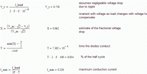
I have made an estimate. The image is from the MathCAD worksheet. I mgiht be off by a factor of 2, but it makes the point.
Assuming the VSPS draws 20mA,
-with 6800uF capacitance, the diodes conduct 2% of the time, and the maximum current is 1.2 A.
-with 220uF capacitance, the diodes conduct 10% of the time, and the maximum current is 0.2 A.
My arguement is that 1A current spike in 200 microseconds (vs. 200mA in about 1 millisecond) does more to mess up the sound than the ripple reduction from 750mV to 25mV p-p does to improve it.
/R
Attachments
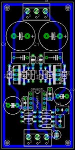
I want to make this design as my final for my preamp...any comments or suggestions before I etch it?
It:
- is dual mono with a ground plane
- uses LM317/LM337 regulators per channel
- has power at one end, signal at the other
- uses Wima FKP2 polypropylene caps for RIAA
😉
It:
- is dual mono with a ground plane
- uses LM317/LM337 regulators per channel
- has power at one end, signal at the other
- uses Wima FKP2 polypropylene caps for RIAA
😉
Attachments
If the vsps draws so liitle current, what's the advantage of using a large transformer?
That's an interesting one. First, "because it sounds better". I'm pretty confident on that one, having tried various transformers in many different situations. But, whats the "why" behind it? There I'm still out of my depth. I haven't figured out a really good reason.
One possibility is the lower impedance and/or larger magnetic core and/or better regulation. I frankly admit that's hard to justify, given the minute load currents.
Another is that larger transformers are better able to filter out power line noise. Well, maybe, but...
My best guess is related to the conduction angle discussion, in that the bigger trannies are better able to absorb the diode switching noise and current spikes. Something about LC tanks and what not. Emphasis on guess.
/R
PS. The PCB looks fine, MAXW, though I didn't go through it rigorously.. Provided you know that those are the sizes of components you will use, I'd say give it a shot.
So what would be the minimum VA transformer to achieve balance between great sound and practicality?
The minimum I should think is 50VA. In toroids, this is usually a sweet spot in the pricing, $25 or so. Its still small/cheap enough to consider going dual mono at some point. Widely available.
Dual mono 50VA would be cool... perhaps not of huge practical use, but definitely cool...
Quality counts too, of course.
-rjm
Dual mono 50VA would be cool... perhaps not of huge practical use, but definitely cool...
Quality counts too, of course.
-rjm
You're right. The price difference between the 30VA and 50VA is quite small. But going up to 80VA is a bit pricier. The Multicomp encapsulated toroid from Farnell looks ok. (No Plitron's here.)
The Toroid brand quad secondary encapsulated transformer looks good also for dual mono application without having two separate transformers.
The Toroid brand quad secondary encapsulated transformer looks good also for dual mono application without having two separate transformers.
i am using 2 x nuvotem talema 50va torriod from RS components for my psu.
the psu was taken from a previous project and thus already have much capacitance in it. after the caps, it is regulated by lm388, adjusted to 15v.
during the short listening session, it sounded great to me. no complains. i should really try a low capacitace supply to see if i like it...
but i am toying with the idea of using one 12v sla battery to drive the vsps. this would require a dc-dc convertor to boost the voltage up to about 15v before going into the 12v regulators at the vsps board. i have already ordered 2 lm2388 boost converter chips with the intention of running it at 200khz for the switching transistor, one chip for +15v, the other for -15v.
anyone tried something similar?
I tried to slow down my supply by inserting resistance around the rectifier circuit- 10 ohms in each AC leg of the rectifier, and 10 ohms in series with the rails off the rectifier. This should slow down the charge time / peak current more than even 220uF caps. The noise was slightly less than before when listening with the volume all the way up. There may have been a slight improvement in midrange clarity, but I'm not absolutely positive yet. I think I might be at the limits of my turntable and cartridge, rather than this preamp. I'm still going to try the small capacitance, low resistance approach. For now, I'm happy with the preamp- just not with the cartridge. It is way too layed back in the upper midrange, lower treble. Also, there is some brightness at the very top end. I'm assuming it may be from the wright mod. Anyone have any suggestions as how to modify the RIAA curve to suit my cartridge? I would like to bring out more upper mids, lower trebles. Probably in the 4-8KHz region, but without boosting the top end any more than it already is.
lm2588, not lm2388...
sorry if i confused anyone. i meant LM2588 chips.
attached is the schematic i simulated. it gave a Vout p-p ripple of 32.94mV.
garbage said:i have already ordered 2 lm2588 boost converter chips with the intention of running it at 200khz for the switching transistor, one chip for +15v, the other for -15v.
sorry if i confused anyone. i meant LM2588 chips.
attached is the schematic i simulated. it gave a Vout p-p ripple of 32.94mV.
An externally hosted image should be here but it was not working when we last tested it.
OK, finished my final VSPS. It has a buzz that I think is a grounding issue that I need to sort out but apart from that its good 🙂

An externally hosted image should be here but it was not working when we last tested it.
An externally hosted image should be here but it was not working when we last tested it.
Re: lm2588, not lm2388...
So the advantage is less ripple and noise over a normal PSU?
garbage said:
sorry if i confused anyone. i meant LM2588 chips.
attached is the schematic i simulated. it gave a Vout p-p ripple of 32.94mV.
An externally hosted image should be here but it was not working when we last tested it.
So the advantage is less ripple and noise over a normal PSU?
maxw said:OK, finished my final VSPS. It has a buzz that I think is a grounding issue that I need to sort out but apart from that its good 🙂
very neat work! i see you used lots of panasonic fc caps. 😉
maxw said:
So the advantage is less ripple and noise over a normal PSU?
actually i'm not sure. the 7812 regulators on the vsps side have about 40-60mV ripple according to the datasheet.
i think the advantage is using a single 12v sla battery to power the vsps... however, that can already be done if the regulators at the vsps side is 9v or less.
come to think of it, any reason why those regs have to be 12v? i understand that some chips likes higher voltage rails, but most seem fine with 5v.
come to think of it, any reason why those regs have to be 12v? i understand that some chips likes higher voltage rails, but most seem fine with 5v.
12 V regs sre suggested since the capacitor voltage rating and transformer secondary voltages work out to common, available values. Using lower voltages lowers headroom somewhat but otherwise no problem. 15v or even 18v regs can also be used with an appropriate power supply. Check the opamp datasheet for the limits.
/r
completed in chassis
finally completed my VSPS tonight.
wanted to have a cheerful colour for the chassis, so i sprayed it volkswagen beetle green... unfortunately, seems like only myself like the color scheme...
anyways, initially wanted to power the vsps off a single 12v sla. the lm2388 seems not capable of multiple output. i had to use 2 x 12v sla for rails of the opa627.
chassis is a eddystone radio emf/rfi proof aluminium case from farnell at SGD17++.
pics of the vsps below.
pretty in green:
innards, with the 2 x lm2388 chips on the perf board to the left:
finally completed my VSPS tonight.
wanted to have a cheerful colour for the chassis, so i sprayed it volkswagen beetle green... unfortunately, seems like only myself like the color scheme...
anyways, initially wanted to power the vsps off a single 12v sla. the lm2388 seems not capable of multiple output. i had to use 2 x 12v sla for rails of the opa627.
chassis is a eddystone radio emf/rfi proof aluminium case from farnell at SGD17++.
pics of the vsps below.
pretty in green:
An externally hosted image should be here but it was not working when we last tested it.
An externally hosted image should be here but it was not working when we last tested it.
innards, with the 2 x lm2388 chips on the perf board to the left:
An externally hosted image should be here but it was not working when we last tested it.
An externally hosted image should be here but it was not working when we last tested it.
Re: completed in chassis
Looks mint! hehe pun intented 😀
Na, really I like it. Good job 😎
garbage said:i sprayed it volkswagen beetle green... unfortunately, seems like only myself like the color scheme...
Looks mint! hehe pun intented 😀
Na, really I like it. Good job 😎
Since you have included the voltage regulators, I guess you could switch to a linear supply if you wanted to.
12V SLAs into 12V regulators though? And what the heck is an lm2388?
/r
12V SLAs into 12V regulators though? And what the heck is an lm2388?
/r
Re: Re: completed in chassis
hahaha... witty. 😉
hi richard
i meant lm2588, not lm2388... wonder why i keep mixing up these two...
the lm2588 is a dc-dc converter. i used it to output 16vdc so that the 12v regulators at the vsps board can be used. 😀
initially i thought that i can use just one lm2588 to accomplish this. but it turned out that i need two instead.
cheers
garbage
maxw said:
Looks mint! hehe pun intented 😀
hahaha... witty. 😉
rjm said:
12V SLAs into 12V regulators though? And what the heck is an lm2388?
hi richard
i meant lm2588, not lm2388... wonder why i keep mixing up these two...
the lm2588 is a dc-dc converter. i used it to output 16vdc so that the 12v regulators at the vsps board can be used. 😀
initially i thought that i can use just one lm2588 to accomplish this. but it turned out that i need two instead.
cheers
garbage
Doesn't a DC-DC converter defeat the purpose of the batteries in the first place, i.e. no switching noise? Further, you could argue it also largely makes the voltage regulators redundent as well.
Its an interesting approach, though for 12V you could just patch the batteries directly to the op-amp...
/R
Its an interesting approach, though for 12V you could just patch the batteries directly to the op-amp...
/R
- Status
- Not open for further replies.
- Home
- Source & Line
- Analogue Source
- DIY phono preamp - cheap and simple!