This Shure cartridge has an inductance of 720 mH. 450 pF of shunt capacity is way too high. You will have a big electrical resonant peak around 10kHz. The maximum shunt capacity for the Shure V15 (about 500 mH inductance) is around 120pF so the maximum shunt capacity for this cartridge should be around 100pF.
Regards,
Ray
Regards,
Ray
why does the site tell me
"Recommended Load
- 47 kilohms in parallel with 450pf"
then? I don't understand why they would tell me the wrong thing.
"Recommended Load
- 47 kilohms in parallel with 450pf"
then? I don't understand why they would tell me the wrong thing.
I don't know why Shure tells people that. If you model the cartridge as a low pass filter with that termination you will find the frequency response has a peak on the high end and the cutoff frequency is well below 20 kHz.
For example, Shure recommended a 250 pF termination for the V-15. It should be about 120 pF for a maximally flat frequency response and for a maximally flat phase response the value should be about 60 pF. That is the total capacity in the cartridge, tonearm wireing, interconnects and preamp. That low a capacity is difficult to obtain.
Properly terminating a high inductance cartridge is difficult because they require very low capacitance or you will have a resonant peak in the frequency response and the bandwidth will be less than 20 kHz.
Regards,
Ray
q: how do you calculate the optimum capacity/impedance for termination of different cartridges?
You use the formula Q=R*SQRT(C/L) where SQRT means to take the square root. This is the formula for the resonant Q of a parallel resonant circuit. R is the terminating resistance, typically 47K, L is the cartridge inductance and C is the terminating capacitance. The Q should be between 0.5 and 0.7. A Q of 0.5 gives a maximally flat (no peak) phase response and a Q of 0.7 gives a maximally flat frequency response. At these low values of Q the bandwidth is approximatly the resonant frequency of thegiven by F=1/(2*Pi*SQRT(L*C)).
These formulas are approximations, the mathematically exact formulas for the Q and bandwidth are more complicated.
Regards,
Ray
These formulas are approximations, the mathematically exact formulas for the Q and bandwidth are more complicated.
Regards,
Ray
Thanks rjm for the design, I have finished mine 😉
Unfortunetly I wont be able to use mine for a while yet as I have to unpack my TT from storage but it will be used soon.
Unfortunetly I wont be able to use mine for a while yet as I have to unpack my TT from storage but it will be used soon.
An externally hosted image should be here but it was not working when we last tested it.
An externally hosted image should be here but it was not working when we last tested it.
An externally hosted image should be here but it was not working when we last tested it.
An externally hosted image should be here but it was not working when we last tested it.
Very nice
Very nice pcb design maxw.
Hope it sounds as good as mine.
Takes some time to run in.
Look forward to your listning tests.
Very nice pcb design maxw.
Hope it sounds as good as mine.
Takes some time to run in.
Look forward to your listning tests.
1. Has anybody tried using silvered mica capacitors for the RIAA feedback loop? These are available in 0.5% tolerance at Farnell.
2. Is the 4.7 uF Blackgate non-polar output cap an arbitrarily chosen value? Only 10uF is available in our place and I'm wondering if this will suffice.
2. Is the 4.7 uF Blackgate non-polar output cap an arbitrarily chosen value? Only 10uF is available in our place and I'm wondering if this will suffice.
Blackgate
You can get them at the following link
http://www.acoustic-dimension.com
Hope this helps.
ran_ph said:1. Has anybody tried using silvered mica capacitors for the RIAA feedback loop? These are available in 0.5% tolerance at Farnell.
2. Is the 4.7 uF Blackgate non-polar output cap an arbitrarily chosen value? Only 10uF is available in our place and I'm wondering if this will suffice.
You can get them at the following link
http://www.acoustic-dimension.com
Hope this helps.
Re: Blackgate
Thanks
🙂
ebijma said:
Thanks
🙂
Anyone know how to troubleshoot the VSPS?
I had myne running on 12volt lead batteries and unfortunatley hooked up one of the 2 batteries the wrong way.
And now my VSPS is dead, I swapped the OPA2134 for another one but it doesn't help.
Visually everything appears to be right.
It basically sound oscillating at 2hz, just like it has not enough supply voltage. But the 2134 only needs +/- 2.5 V and I measure +/- 9V ((9v batteries during testing)
I got no elco's but Wima MKS on the output, so I con't imagine they broke. And the resistors should be alright as well.
What else can go wrong?
2. Is the 4.7 uF Blackgate non-polar output cap an arbitrarily chosen value? Only 10uF is available in our place and I'm wondering if this will suffice.
The output cap used to block DC doesn;t only block dc, it's really part of a passive higpass filter (output cap and preamp impedance). You can calculate it's corner frequency (-3dB point) with f=1/2*pi*R*C
maxw said:Here are my eagle PCB files just in case anyone in the future wants to use my design.
Hi MaxW,
That's a nery neat PCB design. Maybe you can find it in your heart to help me out with my Phonoclone project, see the thread of the same name.
Looking at your circuit, I have two comments:
1. You are using a ceramic and what looks to be generic mylar film caps in the feedback loop. You might try moving to polypro types, Wima MKPs and such, here.
2. You've separated the regulation circuit and the amp circuit, such that the opamps are separated from thier bypass capacitance by some 10cm or so of wire. You may want to consider moving the cap currently next to the regulator output over to the opamp instead.
If you feel in the mood to mod, that is...
regards,
-rjm
rjm said:Hi MaxW,
That's a nery neat PCB design. Maybe you can find it in your heart to help me out with my Phonoclone project, see the thread of the same name.
Thanks rjm, its the first PCB I have designed so any feedback is appreciated! I would love to try and make a design for the phonoclone, I have free time next week so I will have a go then.
rjm said:Looking at your circuit, I have two comments:
1. You are using a ceramic and what looks to be generic mylar film caps in the feedback loop. You might try moving to polypro types, Wima MKPs and such, here.
Yes they are cheap and generic because quality components are hard to source in NZ unless you want to pay alot. Once I have it running I will try different parts.
rjm said:2. You've separated the regulation circuit and the amp circuit, such that the opamps are separated from thier bypass capacitance by some 10cm or so of wire. You may want to consider moving the cap currently next to the regulator output over to the opamp instead.
hmmm, as this was my first I wasn't aware of such considerations. Maybe I will edit it. I separated them because I was going to use one PSU for a few different components in an integrated pre-amp.
Thanks for the tips! 😉
Of course low dissipation factor film caps like polystyrene and polypropylene are best for filter networks, but space or availability may force other choices. If the 330pF ceramic cap is NPO/C0G it's OK, I've read mixed comments about C0G ceramics in filter networks but by published specs their characteristics are better than polyester/mylar and similar to silver-mica, and they are about the only choice for good quality in surface mount. Avoid Z5U ceramic, consider X7R only if you can't get mylar.
Allen wright mod, how accurate.
On Richard his website it says that the value of R3 is not so cricital.
I've built 2 Hi Z versions of the VSPS with completely different results and I found that basically only R3 was different.
The first one was badly constructed, but sounded very good, I experimented with the gain and at some point the solder joints would go loose everywhere.
So I made a new one that was constructed a lot better:
I used a 1K R2 because I needed the gain for my DL103.
The value for R3 should be 9K according the website, but only approximately. Because I only had 20k resistors available, I used two of them in paralel to get to 10k.
Now the sound was really really bad! My first instinct was to check if the layout was correct and all joints were soldered properly. This turned out to be correct.
When I put another 20K resistor in paralel for R3 to get to 6,7K, the sound was a lot better, but still not as good as with the first build.
I've I read the original website correctly it should be not possible to remove R3 (= original RIAA curve) without getting too much distortion.
My questions are:
- Anyone else has the same experience?
- How accurate should the value of R3 be selected?
- WIll the required accuracy rise with the chosen Gain in respect to frequency response?
- WIll the required accuracy rise with the chosen Gain in respect to opamp distortion?
- Is the effect also depending on the type of op-amp chosen?
Eric,
It would probably be quicker and simpler for you to just try a 9k resistor in your new version. Failing that, just remove R3 entirely and see what you think.
At least so far as the frequency response goes, the proximity to the "true" AW curve is not going to make or break the sound. What you are doing with R3 is making a very - very - slight treble boost. The lower the resistance, the less treble boost. If its audible at all it manifests itself as a slight loss of air.
Its other purpose, though, is to give the feedback loop some impedance at high frequencies. This was important for the lowZ version where the resistance on the inverting input R2 was only 220 ohms. For your hiZ circuit, though, R2 is 2200 ohms and R3 can be removed without compromising the performance of the op-amp.
On another level of complexity, though, playing around with R3 affects the circuit bandwidth and the high frequency gain, and thus plays on the circuit stability. So, yeah, I guess the audible affect could be larger than anticipated based on frequency response considerations alone.
-Richard
I read the whole discussion again and came back to Carlos his comment's where he recommended to put bypass caps close to the + and - of the opamp (when using a OPA2134, which I do).
SO I took the only (cheap) caps I had laying around 470uF an just soldered them directly at the + and - and ground.
And the sound improved dramatically!
This is still an amazing sounding phono pre, if you consider the simplicity and extremely low costs. Hope you succeed with the Phonoclone just as well.
ebijma said:
Hello maxw
The vsps is should work fine with a Stanton 500.
Nice homepage by the way.
You did a good job on your gainclone.
Sorry to see you destroyed the looks of you turntable.
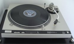
I have restored my SL1600 MKII to its original glory 😀
Attachments
- Status
- Not open for further replies.
- Home
- Source & Line
- Analogue Source
- DIY phono preamp - cheap and simple!