I'm just saying, it does increase the complexity, the number of joints and attachment points, and with that the possibility of driver failure...
The benefit of a larger diaphragm can be had by... using a larger diaphragm. 😉
It also does turn this driver into a one-pony show...
If we did one using two diapragms in series, we could only operate it as not even an open-baffle driver, but as a no-baffle driver... and with that lose some ability to experiment with baffles or enclosures.
On the other hand, if we did a single diaphragm, and built that RE XMX-style welded steel frame with the four walls, we wouldn't lose our ability to run it with no baffle...
...but we would gain the ability to experiment with putting it in different sized baffles, and even enclosures.... even if that meant simply cutting a hole in the spare bedroom door and nailing plywood up over the window so it didn't blow out... 😎
Lol. yeah, all scale is out the window on that plot. I just wanted a rough idea of the flux flowing and any non-linearities, or differences between gaps that might be applicanble to the topology. As soon as we get an idea of what is practically available (has the pole piece thickness been settled?) i.e. tube thickness etc. then we can knock up something a little more realistic.PS. Looks like you spec'd 1"-thick structural steel tubing--might be kinda hard to find in that thickness, and a little heavy, too...
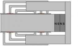
Chris, it's possible that if you were to take a design such as in
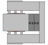
posts #173 and #174, then you could simply opt not to attach the second diaphragm if you wanted more diversity in application. This would probably apply more if the unit was relatively compact (#173).
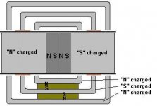
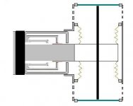
In fact, looking at this motor, unless I'm suffering from some "ate too much", lunch-induced dain-brammage..
I don't see how we establish a magnetic circuit.
Unless the green slugs in the diagram are magnets as well, oriented to present an opposite magnetic force as those magnets in the pole piece.
But, as I've illustrated in my diagram, that doesn't seem to work out... (reference the attached picture)
Some odd polarity issues there.
Am I missing something?
I actually had assumed that we'd have the pole piece extend way out the back (as far as necessary), with the magnets at the base of the pole piece... I guess I was picturing something different than what I was looking at...
I still like the architecture, but we obvoiusly need it to work. 😉
Attachments
... and with that lose some ability to experiment with baffles or enclosures.
Yeah, Chris,
I'm with you on wanting to keep the door open for a pressure version.

I'm not saying dual-diaphragm is necessarily where we should end up going, just serving up food for thought. 🙂
Structurally, I like how we could use two smaller (stiffer) diaphragms to equal one larger one in an OB--it would probably increase our effective bandwidth at a given output.
Fact is, I agree with Vikash that you could just remove the rear diaphragm, and you'd be back to a good candidate for surrounding/enclosing.

...I don't see how we establish a magnetic circuit.
Vikash's drawing (post 167) and FEMM plot (post 177) are good illustrations: You have two floating pole pieces sandwiching a slug or two of NdFeB, so one is the north magnetic pole, and the other is south, as in your drawing. The flux jumps the gaps into the square structural steel sections, and heads back home across the path of least resistance.
The only difference between this and your garden variety tri-gap motor is that each line of flux has to jump two gaps instead of one (why I doubled the magnets in my orig. drawing).
Hi all...
Couple of things:
- Make sure and don't get excited about flux levels until you have a design worked out. Here's the flux graph and B strength plot for the suggested motor (using the 3" OD/1.25" ID neo discs brought up in an earlier part of the thread):
As you can see, using a realistically sized magnet, and a realistic gap width you end up with a gap strength around 0.2 Teslas. A lot more magnet could be used in this design. Also, this uses 1010 grade steel, so that's not the cause of the loss. It's the gap, and relative small amount of magnet.
Rather than use the DDD approach and use the return flux, I'd go with a standard dual or triple gap. You'll maintain a LOT more flux in the gap, because you cut the amount of gap to cross in half. Less air for the flux to flow through. Also a more compact motor. And you'll still get wicked levels of excursion.
Dan Wiggins
Adire Audio
Couple of things:
- Make sure and don't get excited about flux levels until you have a design worked out. Here's the flux graph and B strength plot for the suggested motor (using the 3" OD/1.25" ID neo discs brought up in an earlier part of the thread):
An externally hosted image should be here but it was not working when we last tested it.
An externally hosted image should be here but it was not working when we last tested it.
As you can see, using a realistically sized magnet, and a realistic gap width you end up with a gap strength around 0.2 Teslas. A lot more magnet could be used in this design. Also, this uses 1010 grade steel, so that's not the cause of the loss. It's the gap, and relative small amount of magnet.
Rather than use the DDD approach and use the return flux, I'd go with a standard dual or triple gap. You'll maintain a LOT more flux in the gap, because you cut the amount of gap to cross in half. Less air for the flux to flow through. Also a more compact motor. And you'll still get wicked levels of excursion.
Dan Wiggins
Adire Audio
What would actually be quite clever, in the T-yoke version, would be to use some of the same steel stock, with one wall of it cut out... so that it formed a "U"...
...one flat side being playing the role of the back-plate, the two sides of the U coming up to 'hug' the thing that I've loosely been referring to as 'the top plate assembly' for lack of a better term. 😉
And then the magnets would be secured on top of that, with the pole piece extending up from that.
I'm simply missing where, if the green slugs aren't magnets on the original drawing, the magnetic flux would create a circuit.
If they are magnets, then the polarity issues I mentioned.
😕
I think Stephen Kephart mentioned "where are the grooves in the pole piece?"
The grooves to really do an XBL^2 motor in the pole piece won't be a large expense, I don't expect.
I had two very similar grooves cut into some Koni shock-absorber bodies to extend my spring perch adjustments in my car at a local manual tool and die shop around here for not much money... granted they weren't quite as large...
Dan,
Thanks for the model! 🙂
I think we're actually looking at the ring magnet that lists right below the three-incher:
So that should boost total flux considerably beyond your model. We're also talking about stacking two of them...
IMO, the primary reason we're looking at the DD topology hybrid is that it allows us to put spiders on both sides of the motor for improved support of the moving mass and better control of the VC's radial movement.
Edit: Also to allow twin spaced diaphragms to take some of the bite out of the dipole cancellation.
Thanks for the model! 🙂
I think we're actually looking at the ring magnet that lists right below the three-incher:
(From the seller's website)
Ultimate Ring Magnets - 4.25inch OD - Nickel Plated
N45 - 1.75 inch ID and 0.70 inch thick - these will seriously crush body parts that get between two of them.
$125.00 each (quantities over 10 - email for discount pricing)
So that should boost total flux considerably beyond your model. We're also talking about stacking two of them...
IMO, the primary reason we're looking at the DD topology hybrid is that it allows us to put spiders on both sides of the motor for improved support of the moving mass and better control of the VC's radial movement.
Edit: Also to allow twin spaced diaphragms to take some of the bite out of the dipole cancellation.
OK, bigger magnet is fine, I was using stacked 3" units. Of course, finding 4.25" formers is difficult...😉 You still need to account for the width of the gap, and the fact that with the push pull unit you have two gaps to cross. And the fact that there's no protection of IP violation if the push-pull approach is used.
If you want dual spiders, I'd put one in front of the diaphragm, and one behind the diaphragm. That should give you the support desired.
Dan Wiggins
Adire Audio
If you want dual spiders, I'd put one in front of the diaphragm, and one behind the diaphragm. That should give you the support desired.
Dan Wiggins
Adire Audio
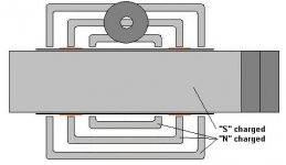
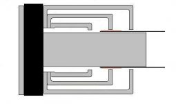
Bill F. said:IMO, the primary reason we're looking at the DD topology hybrid is that it allows us to put spiders on both sides of the motor for improved support of the moving mass and better control of the VC's radial movement.
That's another benefit of that "XMX style" chassis...
If we build the welded tubular steel frame around it, with the plexi (or whatever) walls for the diaphragm to sweep against, we do have a means of holding dual spiders...
One in front of the diaphragm, one behind the diaphragm as normal. 😉
Pardon my kindergarten "MS Paint" skills:
Attachments
Chris,
Yow! Do they even make ferrite donuts that big?! 😱
Otherwise, seems sensible enough. I wonder if the gaps around the edge of the diaphragm do any whistling?
Dan,
True that!
But ever since the former stretched to somewhere around/over 2 feet, I've personally given up hope of using a standard former. 🙂
That would be sensible, provided we decide a double diaphragm isn't worth pursuing.
If you've read our discussion to this point, you know our early thinking on the two-diaphragm question. Do you disagree that using two smaller spaced diaphragms would be the way to maximize diaphragm stiffness and optomize bandwidth for a given output level?
You Adire guys have the jump on us in pondering this naked diaphragm approach, so I'd really love to hear your thoughts on this.
Yow! Do they even make ferrite donuts that big?! 😱
Otherwise, seems sensible enough. I wonder if the gaps around the edge of the diaphragm do any whistling?
Dan,
Of course, finding 4.25" formers is difficult...
True that!
But ever since the former stretched to somewhere around/over 2 feet, I've personally given up hope of using a standard former. 🙂
If you want dual spiders, I'd put one in front of the diaphragm, and one behind the diaphragm. That should give you the support desired.
That would be sensible, provided we decide a double diaphragm isn't worth pursuing.
If you've read our discussion to this point, you know our early thinking on the two-diaphragm question. Do you disagree that using two smaller spaced diaphragms would be the way to maximize diaphragm stiffness and optomize bandwidth for a given output level?
You Adire guys have the jump on us in pondering this naked diaphragm approach, so I'd really love to hear your thoughts on this.
lol...Bill F. said:Chris,
Yow! Do they even make ferrite donuts that big?! 😱
I did disclaimer that it wasn't to scale, right? 😀
We could work through that issue, obviously. 😎
Bill F. said:Otherwise, seems sensible enough. I wonder if the gaps around the edge of the diaphragm do any whistling?
Well, bear in mind that essentially that's exactly what the Phoenix Gold Cyclone does, that I've mentioned a few times in here.
For anyone who isn't familiar with the inner-workings of this very unique rotary servo subwoofer (one of a kind even... only production rotary servo subwoofer ever!), take a look at this page:
A dissection of a Phoenix Gold Cyclone
In the third picture, you can see the moving vane unit, with the plexiglas cylinder removed.
The straight panel who's inner core is white foam is the moving vane unit - the diaphragm.
It simply sweeps against the plexi cylinder walls - or I should say "not quite" sweeps against it (there's no contact made), and there are no air whooshing noises at all.
In fact, if you haven't ever experienced a PG Cyclone... I would urge you to try to hunt down the opportunity. You won't believe the output it provides on a mere 300 watts. 😉
Chris, again I say "You da man!"
Love your guided tour through a cyclone.
I always appreciate people like you who go to the effort to share cool stuff with the rest of us on the web. 😎
Getting back to our baby,
If there is no noise penalty, I believe you (and RE 🙂 ) may be onto something with operating the diaphragm in an open-ended tube. That might be a fine way to lengthen the front-to-back path and improve efficiency while keeping the diaphragm area manageable.
PS. (Referring back to my last post) Dan, whenever you get back to this discussion, I'd really like to hear your thoughts on the specific merits of twin spaced diaphragms.
You know, my scale might not even be that bad... if that's a 24"x24" panel anyway...Bill F. said:Yow! Do they even make ferrite donuts that big?! 😱
I do believe that 13" diameter Ferrite donuts are available.
...and Phoenix Gold. 😉Bill F. said:If there is no noise penalty, I believe you (and RE 🙂 ) may be onto something ...
😀
Fun with FEMM
Attached is a plot of the earlier idea to scale. This should better help to decide whether to discard or carry on with it hopefully...
Mags: Neo 40 (assuming 4.75" OD, 1.75" ID, 0.7" thick)
Steel: 1018
Air gaps: 3mm
Plate thickness: 10mm
Spacing between plates 25.4mm (1")
Pole Length: 212mm (8.35")
Flux in each gap: 0.7 - 0.8 T
Attachments
- Status
- Not open for further replies.
- Home
- Loudspeakers
- Subwoofers
- DIY Parthenon