Serow,
I think we could borrow from Adire's excellent thinking on the matter and use a leg of the metallic "arachnid" spider as a signal pathway. 🙂
RH,
Good thoughts! Keep 'em coming next week!
Bill, referring to the cutaway drawing you posted, have you thought about how you would get the wires to/from the VC?
I think we could borrow from Adire's excellent thinking on the matter and use a leg of the metallic "arachnid" spider as a signal pathway. 🙂
RH,
Good thoughts! Keep 'em coming next week!
Bill F. said:
I think we could borrow from Adire's excellent thinking on the matter and use a leg of the metallic "arachnid" spider as a signal pathway. 🙂
Good idea. Somehow I thought that the wires would have to go away from the former right away. If the gap is big enough to run the wires through, having them attached to the former and run out to the spiders should work fine.
Ideas coming out of the wood work
A dual diaphram will be a real drag. Literally take more power to get it moving. Remember we are displacing air as well as pushing it to get it moving as well as provide a pressure gradient in our rooms. It would tend to balance the system from a viewpoint of motion on both sides of the former. But I question ( without a whole bunch of thought ) the practicality of the two diaphrams. ( flexture as was allready noted and mass that seems to keep getting skipped over. The mass of the diaphram as well as the compliance of the suspension system will be the second most important factor in the efficiency of this driver ) Will there be a benefit that outweighs the losses in terms of efficency. Or will there be an even tradeoff that will perhaps provide some eeven order distorsion cancelation.
Take a note from Dan's discussion of different motor types. I went through this away back when as well. There are of course no magic bullets or free lunches. All design considerations involve compromises. A double diaphram may be a logical or fancifull one. Heat can be mitigated by clever use of the air be pushed around while the motor is operating. If we can keep the flow paths at a fairly low speed there will be a negligable noise contribution and possible a substantial contribution in cooling the voice coils.
Among the many people that are posting and those viewing this thread is there anyone out there with some real world motor design software????
I'd like to see some flux density numbers for the different designs and see what we can do. Refering to gap widths, voice coil diameter, the number of turns of the coil both vertical and layered. The thickness of the top plates or as per Bill's design will we have enough metal to get it going? Some real world sizes of neo pucks or rings and their actual usefullness in non optimum steel components.
Are we going to come up with a cookbook type topology with sizes and construction notes. Or are we going to come up with a series of design principles that can be refered to if someone is determined to build one of these monsters. ( I don't think that there will be a huge market for something like this and if I can contribute something along with the work of others I would be happy to publish what worked and what didn't.
I'll see what I can do for the structural steel members. Regarding their crosections thickness and the like.
I have a structural steel hand book around here somewhere.
Motoring down the path to audio heaven!!!!!!🙂
tre cool😎
Mark
Bill, it appears that you are a man who has been struck by a stroke of genious!Bill F. said:Bill F has attached this image:
Of course, it all does really depend on the availability of the metal... and whether we can really mate them up tightly enough that the flux will flow freely between them... and there's also the possibility that the thickness of the metal walls for those square tubing pieces might progressively be thicker, proportional to the size of the tubing.
It's also got to be available in just the right sizes... even increments... so that our gaps are actually evenly spaced. 😉
And, I'm wondering if you FEMM'ed this design?
It seems to me there's the possibility of the magnetic flux being stronger on the side of the round hole cut in the steel that's closer to the wall of the tubing, as opposed to the sides of the hole that are facing the opening of the tubing.
Just some concerns that I think need to be thought through.
But as I said, I think otherwise this is a stroke of genious! 😎
Personally, I'm even rather liking the thought of a "ghetto" appearing hyper-woofer. 😀
Junkyard wars for audio geeks.
What could BE better?

Attachments
Wow, you guys are crazy. With the looks of it so far, you should call it the "Acoustic Transformer". 😉 That should throw some DIY'ers off.
Sorry for taking this off the current topic. But I had an idea about a topic from pages past, and thought I would post it.
Geo, let's combine your surround idea with mine. Of course it won't work in the present concoction you guys have designed, it should work in a more standard design including the Parthanon. Here's a pic:
Of course it can be scaled down from what it looks above. I think I drew the curves a little large. But you get the idea. I think it will have the advantage of not losing Sd from the surround like other drivers do.
Sorry for taking this off the current topic. But I had an idea about a topic from pages past, and thought I would post it.
Geo, let's combine your surround idea with mine. Of course it won't work in the present concoction you guys have designed, it should work in a more standard design including the Parthanon. Here's a pic:
An externally hosted image should be here but it was not working when we last tested it.
Of course it can be scaled down from what it looks above. I think I drew the curves a little large. But you get the idea. I think it will have the advantage of not losing Sd from the surround like other drivers do.
Vikash,
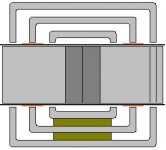
You nailed it--that's how the flux flows through the motor.
Looks like you're tidying up the whole mess visually--cool. It might also serve to muffle some self-noise. And it looks like it could be more axially compact this way, too. Way to go! 😎 I just hope we can get away with supporting that long, heavy pole at only one end...
Yo Chris,
If that's the case, we can just angle-grind the gap edges to equalize the plate thicknesses at the gaps.
We may have to do a little cutting and welding, but it would be nice if we didn't have to...🙂
If there is any difference, I believe it would be extremely subtle since flux flow through the motor would be much more strongly affected by the gap impedence than by any path-length difference in the steel. Flux can be thought of as similar to electricity in that way.
Even if two sides of the gap were more flux-dense, it would only affect total BL--it wouldn't have any effect on linearity.
You nailed it--that's how the flux flows through the motor.
Looks like you're tidying up the whole mess visually--cool. It might also serve to muffle some self-noise. And it looks like it could be more axially compact this way, too. Way to go! 😎 I just hope we can get away with supporting that long, heavy pole at only one end...
Yo Chris,
... and there's also the possibility that the thickness of the metal walls for those square tubing pieces might progressively be thicker, proportional to the size of the tubing.
If that's the case, we can just angle-grind the gap edges to equalize the plate thicknesses at the gaps.
It's also got to be available in just the right sizes... even increments... so that our gaps are actually evenly spaced.
We may have to do a little cutting and welding, but it would be nice if we didn't have to...🙂
It seems to me there's the possibility of the magnetic flux being stronger on the side of the round hole cut in the steel that's closer to the wall of the tubing, as opposed to the sides of the hole that are facing the opening of the tubing.
If there is any difference, I believe it would be extremely subtle since flux flow through the motor would be much more strongly affected by the gap impedence than by any path-length difference in the steel. Flux can be thought of as similar to electricity in that way.
Even if two sides of the gap were more flux-dense, it would only affect total BL--it wouldn't have any effect on linearity.
What would be the effect of having a diaphragm on either end. Any benefits? I had an idea when I was trying to make a perfectly symmetrical design a while back that may provide the required support for the pole piece via slits in the former. Considering the size of this thing, it may be feasible without reducing the former strength considerably.
The flow of flux in two directions assumes that the VC's will be wired in opposite arrangement to each other right?
I think we need a femm plot pretty soon...
The flow of flux in two directions assumes that the VC's will be wired in opposite arrangement to each other right?
I think we need a femm plot pretty soon...
With the design you guys show right now, isn't there an issue with heat around the magnets like what Dan Wiggins described earlier? After all with such a long former and using dual spiders I'm guessing your mass is going to be very high, and this means that efficiency is going to be pretty low.
Also, why the use of dual spiders? If you are already using one of Adire's liscenses, why not the other? After all, from what I understand you can get any amount of Cms you desire with only one set of their Arachnids. Also I'm not big with the dual spider design. Any nonlinearities get magnified which can throw off your curve. Also it provides another glue joint that can go bad. I think it would be better to K.I.S.S. 😉
Also, why the use of dual spiders? If you are already using one of Adire's liscenses, why not the other? After all, from what I understand you can get any amount of Cms you desire with only one set of their Arachnids. Also I'm not big with the dual spider design. Any nonlinearities get magnified which can throw off your curve. Also it provides another glue joint that can go bad. I think it would be better to K.I.S.S. 😉
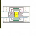
Vikash said:I think I've finally figured the motor out. I've highlighted how how I think the circuit works (please confirm), and also a more symmetrical support leaving the diaphragm better exposed. Supporting the pole piece may require some additions.
Could you cut away some of the material in your pole piece like XBL^2 does? That should reduce some stray flux and flatten out your BL curve.
Also, maybe it has been said earlier, but what is the point of having the flux flow in opposite directions? Why not send all your flux into three gaps and use a single coil? This should reduce inductance quite a bit in the design, reduce cost, size, and still offer an extremely long throw.
What would be the effect of having a diaphragm on either end. Any benefits?
Posts 155, 157, and 160 are the beginning of just such a discussion...
...support for the pole piece via slits in the former. Considering the size of this thing, it may be feasible without reducing the former strength considerably.
Yeah, I've wondered about that, too. So far, all the ways I picture it, the execution would greatly complicate fabrication and assembly...
The flow of flux in two directions assumes that the VC's will be wired in opposite arrangement to each other right?
Right again. It amounts to siamese-twinned motors joined at the buttocks. 😉
I think we need a femm plot pretty soon...
Femm plot--is that a scheme one of Dr. Evil's Fembots might hatch to do in one of Her Majesty's secret agents?

Ahh. Keeping up with all the posts in this discussion is a full time job! A dual diaphragm does seem intuitive. Seems like the last piece in a completely linear system to me.Posts 155, 157, and 160 are the beginning of just such a discussion...
Yeah, I've wondered about that, too. So far, all the ways I picture it, the execution would greatly complicate fabrication and assembly...
I suppose it's too simple to base it on the notion that two smaller diaphrams that displace the same amount of air as one is better.A dual diaphram will be a real drag. Literally take more power to get it moving. Remember we are displacing air as well as pushing it to get it moving as well as provide a pressure gradient in our rooms. It would tend to balance the system from a viewpoint of motion on both sides of the former. But I question ( without a whole bunch of thought ) the practicality of the two diaphrams. ( flexture as was allready noted and mass that seems to keep getting skipped over. The mass of the diaphram as well as the compliance of the suspension system will be the second most important factor in the efficiency of this driver ) Will there be a benefit that outweighs the losses in terms of efficency. Or will there be an even tradeoff that will perhaps provide some eeven order distorsion cancelation.
For me it boils down to the engine power we have available. How much will a single, or two smaller diaphrams weigh? What's the potential weight of the former, and how much force will the motor generate?
Yes I see that too. Off the top of my head, a simple method could make use of a long bolt, then the only issue is cutting the slits in the former to allow it to travel. Let me ponder a little and see if we can find a simple method for this...So far, all the ways I picture it, the execution would greatly complicate fabrication and assembly
What will the former be made of? And what is the envisioned weight of the pole piece?
Attachments
Bill F. said:Vikash,
I just hope we can get away with supporting that long, heavy pole at only one end...
I have a limited understanding of flux flow, but it seems to me that you could machine the pole piece like this to without compromising the effectiveness of the magnetic circuit. It would however greatly reduce the moment acting at the attachment point.
Eric
Attachments
Eric,
Yup, that would work just fine. You could remove even more material without affecting flux flow--FEA could tell you how much.
Only trouble is the additional cost of the boring...
Vikash,
Lookin' good. (considering it's still a monstrosity...) 😀
😀
Yup, that would work just fine. You could remove even more material without affecting flux flow--FEA could tell you how much.
Only trouble is the additional cost of the boring...
Vikash,
Lookin' good. (considering it's still a monstrosity...)
😀FEA
Attached is femmbotplot to get started. Betwen 0.5 - 0.6 T in the gaps. Suprisingly uniform (only ~0.1 T more in the smallest circuit gaps)
D/L my CorelDraw and Femm files if you like.
Attached is femmbotplot to get started. Betwen 0.5 - 0.6 T in the gaps. Suprisingly uniform (only ~0.1 T more in the smallest circuit gaps)
D/L my CorelDraw and Femm files if you like.
Attachments
Vikash,
Thanks for doing that plot and saving me the trouble. 😎
It's a great illustration of another side benefit of this topology. Notice that when one coil is entering the slightly higher flux density of the inner gap, the other coil is entering the slightly lower flux density of the outer gap. The net result cancels the difference! Isn't that just divine?
PS. Looks like you spec'd 1"-thick structural steel tubing--might be kinda hard to find in that thickness, and a little heavy, too...
Vikash...
The problem with dual-diaphragms in this scenario is that they are both in-phase with each other... so getting higher output would not only be an issue, but it would even potentially cause some minor degradation (cancellation) depending on spacing between them, and frequency played.
The reason dual-diaphragms work in drivers like the ServoDrive ContraBass and BassTech7 is because they are out of phase, on either side of an enclosure.
With this driver, that's not possible though.
Let me know what I'm missing, to outweigh the potential additional complexities such as more componentry, more joints, attachment points, etc! 😕
Chris,
Your point is very valid in the world of pressure trasducers (boxed), but since we're talking velocity transducer (open-baffle), twin spaced diaphragms operating in-phase will actually boost on-axis output.
In an OB, the primary detriment to on-axis SPL is the degree to which the high pressure from the front of the diaphragm escapes into the low pressure of the rear of the diaphragm. But when you have two spaced OB diaphragms operating in-phase, the pressure from the front has to travel farther--all the way to the rear of the 2nd diaphragm--to be cancelled (the space between the diaphragms is essentially neutral-pressure).
So, in this case, twin diaphragms essentially gives you a larger effective diaphragm.
Your right about frequency-dependant cancellation between the diaphragms, but that would occur well above 100Hz, and I'll be amazed if we'll be able to make this monster work well above 50Hz...
- Status
- Not open for further replies.
- Home
- Loudspeakers
- Subwoofers
- DIY Parthenon