Re: Fun with FEMM
Anyone care to model up the motor that I posted above, to compare our magnetic flux in the gaps?
Unfortunately, I don't know the dimensions of the 13" diameter Ferrite slugs...
And I also seem to have neglected to add the grooves in the pole piece in my diagram... I did intend to include them...
As Dan mentioned, getting 4.25" diameter formers will be tricky... to say nothing of >4.75". 🙁Vikash said:
Mags: Neo 40 (assuming 4.75" OD, 1.75" ID, 0.7" thick)
Anyone care to model up the motor that I posted above, to compare our magnetic flux in the gaps?
Unfortunately, I don't know the dimensions of the 13" diameter Ferrite slugs...
And I also seem to have neglected to add the grooves in the pole piece in my diagram... I did intend to include them...
Bill,
Twin diaphragms would be fine for a dipole, but I see a lot of complexity compared to a single larger diaphragm with no benefits... I like to stick with one if possible.
Chris,
There are some standard ferrites that are nice and big - 8.375" OD, 3.5" ID, 1" thick. The 10" and 13" OD ones are available, but quite a bit more expensive and difficult to work with (prone to breaking, too). I'd go with a standard 220 unit (8.375" OD) listed above as a good starting point, if you wanted to go with ferrite. Any more, though, on a per unit flux basis, neo is as cheap as ferrite. A lot fewer options in terms of the shape of the neo, though!
Vikash,
I see the problem...🙂 Your air gaps are WAY too narrow; a width of 0.125" (3mm) is tiny. Leaving even a really tight clearance - say 0.02" on either side of the voice coil, tighter than I've ever seen in production on a high excursion woofer - you are down to 0.0805" of voice coil width. Then there's the former, which for a standard aluminum/spun lace version is 0.05" thick. So we're down to 0.03" width for the wire. You'd be lucky to fit two layers of 27AWG wire in there, if that. And for the dimensions you give, that would be a 7.5 Ohm DCR per section of winding - a dual 8 ohm voice coil driver. At best. And I'd be really worried about rocking/scraping.
A more typical gap used in high excursion drivers would be about 0.435" wide, or 11mm wide. Nearly 4X what you have dialed in. Note this is a gap width used in our Brahmas and Tumults, which are still quite tight for the amount of stroke and impedance we have.
Dan Wiggins
Adire Audio
Dan, 11mm! lol. ok, I see where you're coming from now. I had no idea we were looking at that kind of gap space.
A quick plot shows at best 0.4 T in a 11mm air gap.
A quick plot shows at best 0.4 T in a 11mm air gap.
Yep...🙂 I went with 12.7mm (0.5") for my example in this thread, to allow for whatever winding is required. I figured low impedance, thick gauge wire is what's desired, so pretty thick voice coils overall. And with a longer former, I'd like to go with a few layers of Kapton over the aluminum as well (rigidity) which adds another 0.03" thickness or so...
Dan Wiggins
Adire Audio
Dan Wiggins
Adire Audio
DanWiggins said:
Rather than use the DDD approach and use the return flux, I'd go with a standard dual or triple gap. You'll maintain a LOT more flux in the gap, because you cut the amount of gap to cross in half. Less air for the flux to flow through. Also a more compact motor. And you'll still get wicked levels of excursion.
Dan Wiggins
Adire Audio
That's what I said.

The other benifits are lower inductance, lower Mms, and probably reduced cost.
Hey guys, do you have a link to these neo magnets you plan on using? I found some at McMaster-Carr that offer 345 lbs. of pull at $122.50. I thought I would mention it in case it is a better deal.
Posts that are darn impressive!!
Now we are getting somewhere!!!
We have a gap posted by Dan that is realistic given the throw we are aiming for and the propensity of objects in motion to want to keep in motion. And the suspension will not be perfect no matter what we try to do there will be a degree of rocking back and forth so 12.7 mm makes sense.
Pole piece could be heavy wall tubing. You can get hot rolled seamles tubing with wall thicknesses of up to an inch under 4" in diameter and up to an inch and a quarter over 4". Would require no or little boring. Keep in mind that the thickest 1018 structural tubing I could find is 4"by 4" and it is 0.500" The interior is not perfectly flat and there are weld flash and so on inside. Tubing is available in 5", 6", 8" and so on. These sizes can be had at 0.500" wall thickness.
As for the ferrite ring idea where are you planning on getting this thing charged??? It is a large magnet that will require a fixture. It may be larger than most places can even accomodate. Stick with the neo!!
The motor is going great!!
Now we need some better simulations as per Dan's recomendations on the gap and the practical thickness of tubing that we can come up with. Keep in mind that a hollow pole piece may be helpfull in being part of the return path. Simulate it a see what happens.
We are using a "T" shaped pole section at the top plate junctions??
Bill does your motor design require perfect fits on the tubes??
Geolemon between you and Bill with a push and a shove from Dan I think that a truly well engineered motor is in the works.
Thumbs Up
Mark
Re: Posts that are darn impressive!!
It seems to be very much in keeping with this sort of "junkyard wars" thing we seem to have going here... salvage steel for the top plate assembly and all... 😀
It will make acheiving a real performer a much more satisfying thing, IMO.
That must be simply the longest you could find by you.. it simply doesn't make sense that the real heavy duty stuff (particularly with walls that thick.. that's ideal, we can cut grooves into that!)... It must be available in significant lengths... certainly way longer even than we would need. 😉
I do know of somewhere to get it charged. 😉
It makes sense (law of supply vs. demand) that the big slugs would be quite pricey... how many drivers do you know of that use 13" diameter slugs? 😀
So, it doesn't seem like the best bet in this case.
But seriously, making a neo sandwich out of our "top plate assembly" and back plate is just fine with me. Seems like we've got a much finer control over exactly how much flux we want to flow that way also... essentially, a 'modular magnet'. Cool! 😎
I'm particularly pleased with where it seems our expense is going.
It's easy to do big thinks with big money.
It makes it more of an acheivement to do bigger things with less money involved.
This is a very cool idea, IMO...mwmkravchenko said:Pole piece could be heavy wall tubing. You can get hot rolled seamles tubing with wall thicknesses of up to an inch under 4" in diameter and up to an inch and a quarter over 4". Would require no or little boring.
It seems to be very much in keeping with this sort of "junkyard wars" thing we seem to have going here... salvage steel for the top plate assembly and all... 😀
It will make acheiving a real performer a much more satisfying thing, IMO.
Only coming in 4" lengths is a bummer... 🙁Keep in mind that the thickest 1018 structural tubing I could find is 4"by 4" and it is 0.500" The interior is not perfectly flat and there are weld flash and so on inside. Tubing is available in 5", 6", 8" and so on. These sizes can be had at 0.500" wall thickness.
That must be simply the longest you could find by you.. it simply doesn't make sense that the real heavy duty stuff (particularly with walls that thick.. that's ideal, we can cut grooves into that!)... It must be available in significant lengths... certainly way longer even than we would need. 😉
I really only suggested it because I knew of it's existance (13"), and the relative cheapness of Ferrite...As for the ferrite ring idea where are you planning on getting this thing charged??? It is a large magnet that will require a fixture. It may be larger than most places can even accomodate. Stick with the neo!!
I do know of somewhere to get it charged. 😉
It makes sense (law of supply vs. demand) that the big slugs would be quite pricey... how many drivers do you know of that use 13" diameter slugs? 😀
So, it doesn't seem like the best bet in this case.
But seriously, making a neo sandwich out of our "top plate assembly" and back plate is just fine with me. Seems like we've got a much finer control over exactly how much flux we want to flow that way also... essentially, a 'modular magnet'. Cool! 😎
I'm particularly pleased with where it seems our expense is going.
It's easy to do big thinks with big money.
It makes it more of an acheivement to do bigger things with less money involved.
The other benifits are lower inductance...
Actually, I believe the DD topology will give the lowest Le by quite a bit. The counter-wound coils largely cancel each other's inductance...
Just throwin' out a little clarification...🙂
Have a great weekend, y'all.
I'm not sure my technical explanation of a dual diaphram stiffness/weight interaction really got the point across, so I'll simplify the main point.
Take a given diaphram size, say 500 square inches. Two diaphrams of 500 square inches each can be lighter than a single diaphram of that size for a given stiffness. I know it seems counterintuitive, but it really works out that way.
Yes, the complexity increases (well, the diaphrams should be pretty easy to make, whether that is one or two, and the motor structure proposed by Bill and simplified by Vikash makes it easy to mount the second diaphram, but the connections between the two certainly add complexity to the overall design), but the weight decreases.
I don't think I stressed that enough previously. You want to lower the moving mass? Add a second diaphram of the same size as the first!
I also have qualms about a spider in front of the diaphram. Seems like a recipe for some air turbulence noises at high excursions. Maybe that is an unjustified concern. As far as limiting the use for pure dipole application, I don't see that really being the case. If you can put one diaphram in a tube or box "cylinder" and let the diaphram sweep like a piston, I don't see any reason why you can't do the same with two. The cylinder would be longer, but this thing isn't exactly meant to be a space saver anyway! 🙂
Steel with umph
Mr. Geolemon the dimensions I gave for the square tubing were on the cross section. If you have a semi truck and trailer and a 10 ton crane you can get them up to 43' should you desire😉
And yes to simplify is brilliant. To do so and save money in the process is true engineering!!!
MArk
Mr. Geolemon the dimensions I gave for the square tubing were on the cross section. If you have a semi truck and trailer and a 10 ton crane you can get them up to 43' should you desire😉
And yes to simplify is brilliant. To do so and save money in the process is true engineering!!!
MArk
Yes, it certainly seems counterintuitive! 😱RHosch said:Take a given diaphram size, say 500 square inches. Two diaphrams of 500 square inches each can be lighter than a single diaphram of that size for a given stiffness. I know it seems counterintuitive, but it really works out that way.
...I don't think I stressed that enough previously. You want to lower the moving mass? Add a second diaphram of the same size as the first!
To quote Alice in Wonderland..."curiouser, and curiouser..."

Do you have any more information on how this phenomenon plays out? It's certainly not directly related to mass... because mass is obviously going to double if you simply add a second, identical diaphragm... so there must be some phenomenon that could explain it.
More or less, I'm curious about that to satisfy my own personal knowledge, because:
Why do we care in this case what our diaphragm mass is, at any rate? 😉
I didn't believe efficiency was a huge concern here... and I was believing we would find an ultra-low Fs to add to our bragging rights. 😀
The problem is, that motor has fundamental problems related to flux flow, as it's not an efficient circuit. The flux isn't directly connected to any of the top plates, of which there are six times as many as a normal subwoofer that might attempt that strategy. 😱
Yes, the complexity increases (well, the diaphrams should be pretty easy to make, whether that is one or two, and the motor structure proposed by Bill and simplified by Vikash makes it easy to mount the second diaphram, but the connections between the two certainly add complexity to the overall design), but the weight decreases.
Check out the FEMM plots above. 😉
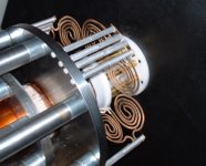
I've attached a picture of the Parthenon's "Arachnid" suspension.I also have qualms about a spider in front of the diaphram. Seems like a recipe for some air turbulence noises at high excursions. Maybe that is an unjustified concern. As far as limiting the use for pure dipole application, I don't see that really being the case. If you can put one diaphram in a tube or box "cylinder" and let the diaphram sweep like a piston, I don't see any reason why you can't do the same with two. The cylinder would be longer, but this thing isn't exactly meant to be a space saver anyway! 🙂
You can see it's size is relatively small compared to the size of the diaphragm, and it's also relatively open, allowing adjacent air to pass. As it reaches higher excursions, it opens up even more...
There's nothing causing an increase in airspeed over that velocity that the cone reaches itself, and we aren't taking a mass of air and compressing it to higher pressures (both of which are the problem with noisy ports, for example)
Regardless, we'll need at least one of these things on the sub at any rate... so if there was noise, we're not avoiding it by only having one spider, as opposed to two. 😉
Also, we could actually improve things by having two spiders of this type, one in front, and one in rear of the cone:
The "arachnid" spider as Adire used it had eight 'coil springs' if you will.
If we believe we could accomplish our target suspension stiffness with one spider... one set of these eight 'coil springs'...
We could allow for even more airflow (and less noise, if it occurred) by arranging this as four springs in front - and four springs in rear.
I think having a spider both in front and behind the diaphragm is actually in keeping with your goal of ensuring as little air-rushing noises as possible.

 Possibly Dan could comment though, on the likelihood of even fundamentally having air noise past the springs?
I personally can't imagine that would be an issue, just fundamentally.
Attachments
Re: Steel with umph
I was reading that paragraph, and my brain failed to jump from "round tube used for pole piece" to the "square structural tubing" that you were describing there.
I suppose our concern might be in getting a small enough quantity... a 43' section is probably a tad large for us. 😀
Have we considered contacting one of these companies, and asking them simply for some 12" long 'samples' of 6"x6", 8"x8", and 10"x10" structural steel tubing, just as pure product samples for evaluation purposes?
Might be a way to get what we want, in the sizes we require, for cheap.
oh, I'm sorry.mwmkravchenko said:Mr. Geolemon the dimensions I gave for the square tubing were on the cross section. If you have a semi truck and trailer and a 10 ton crane you can get them up to 43' should you desire😉
And yes to simplify is brilliant. To do so and save money in the process is true engineering!!!
MArk
I was reading that paragraph, and my brain failed to jump from "round tube used for pole piece" to the "square structural tubing" that you were describing there.
I suppose our concern might be in getting a small enough quantity... a 43' section is probably a tad large for us. 😀
Have we considered contacting one of these companies, and asking them simply for some 12" long 'samples' of 6"x6", 8"x8", and 10"x10" structural steel tubing, just as pure product samples for evaluation purposes?
Might be a way to get what we want, in the sizes we require, for cheap.
What would you consider an acceptable flux density in the gaps then (considering >12mm)? A flick through the Shiva whitepaper mentions everything but the flux density in the gap (and I assume the width is 10.5mm not 1.05mm). What levels are achieved in the Parthenon motor?Yep... I went with 12.7mm (0.5") for my example in this thread, to allow for whatever winding is required. I figured low impedance, thick gauge wire is what's desired, so pretty thick voice coils overall. And with a longer former, I'd like to go with a few layers of Kapton over the aluminum as well (rigidity) which adds another 0.03" thickness or so...
Is this what you are looking for?
"Oh yeah - flux in the gaps is pretty high, at 0.8T" http://www.adireaudio.com/Files/Dan/Parthenon/
"Oh yeah - flux in the gaps is pretty high, at 0.8T" http://www.adireaudio.com/Files/Dan/Parthenon/
geolemon,
The explanation is pretty simple. I went through it in a technical way previously, but I suspect I wasn't very clear. Two diaphrams could weight less than a single one because each could be less than half the weight/thickness. The combination of the two interconnected spaced diaphrams would give a system stiffness equal to or greater than that of a single diaphram, but with less combined weight due to the much thinner/lighter design of each independent diaphram.
It is the same reason why a carbon composite sandwich consisting of 1/4" skin, 1" balsa or foam core, and 1/4" skin is both stiffer and lighter than a solid laminate of 3/4" thickness. Though the solid laminate contains more carbon (and thus weight) than the sandwich, the increased geometrical stiffness resulting from having a core more than makes up for that. In the case of two spaced diaphrams, the connections between them essentially play the role of the "core", and each diaphram is a "skin" that can be reduced by more than 50% weight each compared to what a single diaphram would require.
It was indeed Raoul, thanks.
Considering the 6 gap connceptual model: why is halving the flux in each gap and doubling the gaps not as good an approach (physical complexities aside).
i.e.
3 gaps @ 0.8 T each vs 6 gaps @ 0.4 T each
Two VC's, double the wire thickness, half the layers. Lower impedence. Lower Le.
I don't know enough to understand all the effects of this, or whether I've missed something obvious. Could someone put my mind at ease...
Sounds familiar: double the diaphragms, half the size, increase in overall stiffness 😀
Dan: figured low impedance, thick gauge wire is what's desired
Considering the 6 gap connceptual model: why is halving the flux in each gap and doubling the gaps not as good an approach (physical complexities aside).
i.e.
3 gaps @ 0.8 T each vs 6 gaps @ 0.4 T each
Two VC's, double the wire thickness, half the layers. Lower impedence. Lower Le.
I don't know enough to understand all the effects of this, or whether I've missed something obvious. Could someone put my mind at ease...
Sounds familiar: double the diaphragms, half the size, increase in overall stiffness 😀
A few more magnet options:
3" OD x .75" thick disc of N40. Smaller OD might give more former options, no central hole might mean similar overall flux to the 4.75" ring magnet... not sure, can someone check it out? $80 each, quantity discounts possible.
2" OD x 2" thick N42. Not sure these would be large enough dia.
3" OD x .75" thick disc of N40. Smaller OD might give more former options, no central hole might mean similar overall flux to the 4.75" ring magnet... not sure, can someone check it out? $80 each, quantity discounts possible.
2" OD x 2" thick N42. Not sure these would be large enough dia.
Ideally, you want more of your BL to be from B, not from L. If it's from B, then you have less compression issues (thermal or flux). If it's from L, you have more compression issues, as well as typically more inductance.
Also flux efficiency. The more steel and the more air gaps in your flux path, the lower the total flux in the system. You get more flux flow from your magnet with shorter steel paths and the fewest/narrowest air gaps possible.
Lastly, the longer the former, the wider the gap to avoid scraping during rocking. Using 6 gaps in opposite polarities as in some of the designs in this thread will require a wider gap, simply from a physical clearance issue. For a given angular displacement (which is a function of stroke, suspension stiffness, and mass) you will have a longer radial displacement of the end of the former. Even with dual spiders you'll still have this concern. The taller the motor, the wider the gap must be to account for it.
This is why there's a point of diminishing returns with fewer layer, heavier gauge voice coils. For example, consider the JL W7 and the Brahma. Both have the same magnet weight, and about the same magnet area. The W7 has a long 2 layer voice coil, the Brahma a short 4 layer voice coil. The W7 has about 40% more DCR, which you would think would give it a higher BL (typically BL increases as DCR increases). Of course, the BL of the W7 is down around 11, about 60% of the BL of the Brahma... Gap width, and keeping as much of the voice coil in the flux as possible is what gives you efficiency.
Basically, it's not just the flux you have, but how you use it. Choices about the design of the driver will affect how you can use your flux. The longer the motor, and the more rocking you have, the wider the gaps, meaning you will restrict flux flow.
Dan Wiggins
Adire Audio
RHosch,
I thought this was interesting. The one magnet version of what I've been modelling is only ~0.1 T down in the gaps then with two magnets. Smaller disk magnets may do equally ok, but there goes the option to vent the pole piece...
Edit: infact I think the 3" magnet works out better with 1.5" contact area on each half vs 4.25" ring which works out to 1.25" ((4.25" OD - 1.75" ID / 2). Plus the 3" magnet you mention is 0.05" thicker. This is all at the expense of the pole vent possibility though.
Red line: 1 Magnet, Black line: 2 Magnets
Attachments
- Status
- Not open for further replies.
- Home
- Loudspeakers
- Subwoofers
- DIY Parthenon