Wow, N45! 😎
And it allows the option of a pole vent if we ever return to considering a pressure transducer.
Looks like it might be the bee's knees...
And it allows the option of a pole vent if we ever return to considering a pressure transducer.
Looks like it might be the bee's knees...
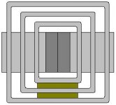
Bill F. said:AlNiCo motors with a section of square tubing serving as the return circuit
Here is an example pic to serve as a reference...
dave
Attachments
Here is a page explaining the different grades of NdFeB magnets, if anyone is interested:
http://www.stanfordmagnets.com/magnet.html
scroll down to section 3 for the different types.
--
Brian
http://www.stanfordmagnets.com/magnet.html
scroll down to section 3 for the different types.
--
Brian
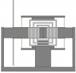
Um... Bill, excuse me for being really dumb for a moment. What exactly have you drawn? In particular, which direction is the speaker pointed... up/down, left/right? In/out?? 🙂 I'm having a difficult time locating all the meaningful bits in your sketch... perhaps it is the assymetry that is throwing me off. BTW, why is it assymetric??!?
lol, you made my brain hurt, and I usually have no problems visualizing things. 😀
lol, you made my brain hurt, and I usually have no problems visualizing things. 😀
BrianGT said:a page explaining the different grades of NdFeB magnets
Thanx for that... some good alnico info there too...
dave
lol, you made my brain hurt, and I usually have no problems visualizing things.
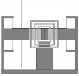
Yeah, I guess that wasn't exactly crystal clear--sorry!
Part of the cofusion may come from the fact that I put the diaphragm between the spiders to better distribute its weight.
Lemme try again--labeled this time.

Attachments
Ah, that makes much more sense now! 🙂 Instead of a spider on each side of the diaphram, I would prefer to see a spider on each side of the motor (as you have it in your sketch) but with the diaphram cantilevered on one end. With wide spaced spiders, the moment created by an offset cantilevered diaphragm on one side would be easily handled by the suspension. Probably not even requiring a guide-rod type of setup.
I'm still interested in some type of elastic/elastomeric bands for a linear suspension. Definitely cheap, and easy for the DIY type. When I get more time I'll draw up a few sketches to see how practical the idea is. Otherwise, the two spider system shown looks pretty easy.
I really like the motor structure... very easy. How about availability of low-carbon steel square tubing in appropriate sizes? I'll check on that if no one gets to it before I do.
I can only imagine how powerful a 4" ring of NeFeB would be. I have a couple of 1.5" OD rings, 1/4" thick here at home, and they are enough to bring blood out of a finger if not handled carefully!
Me thinks the brains are out in full force captin
Now we are getting somewhere. Impressive!!
Now we need some critiques of the motor circuits above. Anyone have a simulator that can work with different grades of steel. The structural stuff in the diagrams is most likly 1018. We are looking at a loss in possible flux density. But how much. I can't find my old permiability tables!! Anyone out there ??
Mark
P.S. This is possible becomeing an easy design if it will work. Something that can be done on a decent sized drill press with a minimum of machining.
😀
RHosch said:I can only imagine how powerful a 4" ring of NeFeB would be.
I imagine it gathering up any ferrous materials within at least a foot radius.
As the website mentioned, it would be quite interesting to put a pair on a dowel rod, with the poles arranged for repulsion, and watch the top magnet levitate, as gravity pulls it down. I would imagine it would bounce a bit too. I am curious about how much force would be required to hold two of these together in this setup.
I would be seriously scared to handle a pair of these things, as I have pinched my fingers between some much smaller NdFeB magnets before, and it isn't pleasant.
--
Brian
Instead of a spider on each side of the diaphram, I would prefer to see a spider on each side of the motor (as you have it in your sketch) but with the diaphram cantilevered on one end.
Ok . . . Does this suit you better? 🙂
Slightly inferior distribution of mass, but if it matters as little as you think it will, I'll go along with it.
I guess it is a tad easier on the eyes, too . . .
Attachments
Points of Ponderment in the non firmament
Mr. Bill Im going to stab into the dark with your diagram and start asking what is what.
The grey boxes are what 1/4" stuctura tubing sections??????
Bent plate as per the other picture by planet10???
I understand the concept of a return path and I'm thinking that this might work.
THe other grey rectangles are the neo pucks????
And the machining will be comprised of cutting a gap clearance and turning a pole piece???
If this is it I'm impressed by your simplification!!
If it works out in a simulation then lets go for it. We are not looking at a lot of money here. The neo pucks will cost the most. Centering them will be a pain in neck. But it can be done with a slow set adhesive and some proper fixtures. We may have to make some spiders for the prototype or steal Dan's spring array.
Now all we have to do is get together a group order on some voice coils. Or twist Dan's arm to sell us some. (heh heh)
🙂 🙂 🙂
Mark
Bill F. said:
Ok . . . Does this suit you better? 🙂
Slightly inferior distribution of mass, but if it matters as little as you think it will, I'll go along with it.
I guess it is a tad easier on the eyes, too . . .
Ah, yes, looking very nice. Very simple, easy construction, easy to obtain magnets, good arrangement for support of the guide rod, and the support structure could be made as elegant and/or "trick" as desired to produce a nice polished end product... or a workable "garage" unit, as desired.
Any problems with heat dissipation from the VC?
One last thought... if this is going to be a true dipole sub, and you've already mirrored the motor structure to provide a push/pull arrangement (regardless of whether it is really necessary, as it seems trivial to add it to this design), why not mirror the diaphram as well? That is, actually add a second diaphram on the backside of the motor, with lightweight rods connecting them at various points on their perimiters. That would be one very efficient way (in terms of weight) of stiffening the cone, since stiffness increases with the cube of thickness and you would pick up a whole lot of geometrical thickness by going that route.
In fact, flexing of the diaphram has been a concern of mine from the outset. Moving a large panel back and forth dozens of times a second, through a 6"+ range of motion, is going to create a lot of air loading and force against the diaphram. Adire used a carbon/balsa sandwich, which is what I recommended previously, but judging from the pictures I'd be a bit worried about their diaphram given its apparent thickness and my experience with composites. I know such a sandwich (it looks to be roughly 1/2" thick) would be very stiff in your hands, but it would flex under the loading the Parthenon motor generates. I would have been more comfortable with a much thicker core... say 1" or greater, but having two diaphrams with connections to each other would allow for significant triangular bracing of each diaphram.
Any ideas on how a true "dipole diaphram" would affect air turbulence and chuffing sounds? Better or worse than having the air moving around the motor structure exposed directly to the backside? What about radiation pattern... would the second diaphram not promote a truer dipole radiation pattern? (as if that mattered for such low frequencies... 🙂 ).
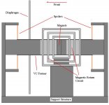
454,
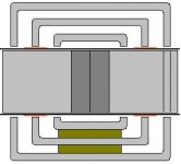
See the cutaway below. 🙂
Mark,
Yes, but I might suggest 3/8" or perhaps 1/2".
Yup.
Righto. Quite a step back from the machine-intensive architecture of the Parthenon, eh?
You're very kind. 😎
See the cutaway below. 🙂
Mark,
The grey boxes are what 1/4" stuctura tubing sections??????
Yes, but I might suggest 3/8" or perhaps 1/2".
THe other grey rectangles are the neo pucks????
Yup.
And the machining will be comprised of cutting a gap clearance and turning a pole piece???
Righto. Quite a step back from the machine-intensive architecture of the Parthenon, eh?
If this is it I'm impressed by your simplification!!
You're very kind. 😎
Attachments
Any problems with heat dissipation from the VC?
Always. 🙂 We'll certainly have to look at that. However, I don't see that this design contains any real compromises in terms of heat dissipation--rather I'd say it could be excellent on that point.
if this is going to be a true dipole sub, and you've already mirrored the motor structure to provide a push/pull arrangement (regardless of whether it is really necessary, as it seems trivial to add it to this design),...
Actually, it seems the natural choice if you want to space the spiders on both sides of the motor... VC former's gotta pass all the way through...
...why not mirror the diaphram as well? That is, actually add a second diaphram on the backside of the motor, with lightweight rods connecting them at various points on their perimiters. That would be one very efficient way (in terms of weight) of stiffening the cone, since stiffness increases with the cube of thickness and you would pick up a whole lot of geometrical thickness by going that route.
Definately an option. It would also serve to lengthen the effective front-to-back path, so bass efficiency would improve. It would add mass, so we'd have to make sure there was enough motor to drive it.
Any ideas on how a true "dipole diaphram" would affect air turbulence and chuffing sounds? Better or worse than having the air moving around the motor structure exposed directly to the backside?
Air will be forced around the motor either way, so it's kind of a moot point, IMO.
Bill, referring to the cutaway drawing you posted, have you thought about how you would get the wires to/from the VC? I imagine the gap would be too small to pass them through, and if you ran them through a hole in one of the sides of the box section the VC would be limited to travelling in the section between the two return paths, if you see what I mean.
Perhaps a axial slot machined in each of the box sections, aligned radially, would allow access to the wires without restricting the travel of the VCs.
Cheers,
Eric
Perhaps a axial slot machined in each of the box sections, aligned radially, would allow access to the wires without restricting the travel of the VCs.
Cheers,
Eric
Ah, yes, looking very nice. Very simple, easy construction, easy to obtain magnets, good arrangement for support of the guide rod,
Actually, I'm hoping the widely spaced spiders will let us skip any sliding contact whatsoever, therefore the "guide rods" would simply support the floating pole piece.
On that front, I suggest that we shoot for radially stiffer spiders. It seem to me that if we cut them out of thin plate, but remove very little material (so they are axially thin and radially thick), we should be able to suspend the entire moving mass (radial load) while maintaining good compliance (axial motion)
I also suggest we shoot for an Fs of 15Hz or higher, as this will net better control and improve dipole bass response above 15Hz.
Excellent. 🙂Bill F. said:...I don't see that this design contains any real compromises in terms of heat dissipation--rather I'd say it could be excellent on that point.
Ah, something was telling me that there was a definite advantage for a dipole application of having spaced diaphrams... path length! Though I suppose that is pretty negligible at the sizes and frequencies we are talking about. In any case, my suggestion was that it could potentially remove mass from the diaphram. Stiffness in a plate is dependent on two factors: thickness of the plate, and modulus of the material. Stiffness increases linearly with modulus, and with the cube of thickness.Definately an option. It would also serve to lengthen the effective front-to-back path, so bass efficiency would improve. It would add mass, so we'd have to make sure there was enough motor to drive it.
Think of my suggestion in this manner: want to make a 1/2" carbon plate stiffer without adding any weight? Simply add a 1/2" core and reduce the skins to a bit under 1/4" each to account for the core weight. The resulting ~1" sandwich would be much stiffer than the original 1/2" solid laminate with no weight penalty. Similarly, if you used two widely spaced diaphrams with a system of connecting rods and triangulation braces, you create a plate system that has an effective thickness equivalent to the spacing of the plates - much greater than a single diaphram could be. Therefore, the thickness of each diaphram could be substantially less than half of what a single diaphram would require.
Note that in this braced system, the effective modulus of the braces becomes the solution of the truss system and not simply a material modulus, and there are other considerations that would require taking a look at, but the idea is sound. Why are bridges built using trusses instead of giant solid plates? Better stiffness/weight ratio. Same would apply to wide spaced diaphrams.
I would throw out a SWAG that if properly designed and optimized (something I'd be happy to assist with, as it would be rather simple using structural FEA) a braced diaphram pair could be roughly 50% lighter than a single diaphram of equivalent stiffness.
Ah well, I'm off for the night... and the weekend. I'll do some more rigorous thinking about this next week. 🙂
- Status
- Not open for further replies.
- Home
- Loudspeakers
- Subwoofers
- DIY Parthenon