PUSH-PULL MOTOR
PUSH-PULL Motor.
Two smaller motors, each with two magnetic gaps, could deliver more HP than one large motor with two gaps, and the symmetry would reduce distortion. This was the idea behind the Push-Pull sketch.
I simulated a magnetic bearing in FEMM. A 0.4" thick grade H40 NdFeB center arc'ed magnet would generate a 0.05 Tesla fringing field at a distance of 2" to a 5" diameter voice coil. The gap flux should be 1.8 Tesla, so a small overhang to the bearing magnet should have a modest affect on BL.
Human hearing will suffer permanent sensitivity loss from long exposures to 85 db. A linesource of five 15" woofers can reach 110-120 db at 20Hz (6,000-10,000 cm^3 + room gain) in the typical listening room. I have four of these 5 x 15" linesources in my HT, but seldom listen over 70 db average SPL.
Bearings and other directions
Mr. LineSource are you thinking that a magnetic bearing would not effect the Le of the coil(s) or the Bl of the motors???
Maybe you are thinking ahead of me. If it was properly placed and the fringe field is indeed as low as you simulated maybe it could work.
I completely agree that two smaller motors working as a push pull will indeed be more efficient. They would be conceling out the even order distortion first and foremost. But a drop in the odd order will come along for the ride as well. There are patent problems. But I seem to remember Bose ( the company with the ravenous patent lawyers ) not willing or being able to prosecute home construction of some of their sub designs. I think that was in the birdhouse design in speaker builder a few years back. George Augspurger also wrote it up with no apparent problems.
Your proposed design is good. Is it a nice napkin sketch or do the dimensions and placements of the parts have some rhyme and reason?
One more thing about loudness and music. Check out the loudness curves on human hearing and see where the thresholds are for the low end. 120db in the extreme low bass is not that dangerous. A good organ concert will expose you to some very loud low bass. Our threshold for hearing an open CCC ( 32' ) is around 108 db. Usually on an organ such a note is played in concert with a 16' rank as well. The two will modulate each other and sound louder. You will hear the 16' CC first and then the roll and rumble of the big daddy. If it is massaging your innards you are being exposed to music above 100db to no ill effect. Take that same organ and sit close and hear the tierce or other high pitched mixtures and you will indeed be pushing your ears to the limit. You will be reminded momentarily by hearing a sort of distortion in your hearing and if you persist you will start killing those beautiful little hairlike receptors in your inner ear. Hearing loss. Non reversable. And it starts from the top down.
Music is a wonderfull thing. It requires our respect, patience, understanding, some love and in this forum some loose marbles.
We are trying to build a driver capable of reproducing concert level low end in our listening rooms. This driver ( parthenon or a knock off or better a design amalgam ) will be able to do that. The holy grail!! Loud and without a box to mess things up.
Think of a quad esl will real balls! (oops getting carried away here)
So now we may have a competing motor design.
Three or even four gaps can be cobled together if we put some ingenuity towards it. The machining is not rocket science. The only part of the motor design that bothers me is using enough magnets to force a saturated field at each top plate pole piece junction. But not more than needed. And the size of the piece of steel needed tomake the pole piece. The top plates can be cut from plate if needed and the turned down. But that pole piece is going to weigh what 10 to 12 lbs yikes maybe more ( time to get out the slide rule )
The other question I have ( having experienced this in the full range design that I worked on away back when ). That if we have to large of a pole piece in relation to the top plate are'nt we going to have a low Bl product?? Because at the junction of top plate and pole pice we are looking for a saturated gap and if we have to much metal in a 4" pole piece then can it be done? I guess the pole piece could be bored out to an optimal thickness or the relationship of the top plate thickness, pole piece real thickness and the available magnetic flux can be balanced. That's what a simulator is for. And those are the answers that are needed before we can get going on a motor.
THe diaphram is a special composite. Good then I'll have to come up with some thing that is light and stiff enough to do the job. I think that Magura's carbon fiber idea and the foam core idea are the places to go for this exercise. Stiff but light.
The springs are not that big a deal once you see how they are implemented. I'm guessing that the copper alloy used was more for the dual purpose of conduction of drive power to the voice coils and a balance with something that will still be springy. Nice touch.
Steel of any kind is not the best conductor for music. More thinking is required on this one. I guess I could fasten an insulated lead to the spring with short lenths of heat shrink slipped over the spring and the wire. It would keep it in place and still be a good conductor. Although it would create a partial self induced inductance ( probably to small to worry about ) OK I'm on a roll next problem, come on keep them comming no fear here🙂
Mark still smiling!!
Boy, I miss this thread for a few days, and we get a bunch of activity! 😎
And I thought people were losing interest.
That being said, one thing we should think about here is...
Do we care if we have an Fs below 10hz?
That is pretty darn low.
Do we care if it's under 20hz for that matter?
What's our goal for that? 😉
And Dan, if we used two spiders, spaced so far apart (as I suggested anyway... an XMX style chassis, with a frame holding one spider out in front of the diaphragm, while also holding another spider in the typical location behind the diaphragm), why would we still need a guide?
Shouldn't that spider - exotic as it is - still control lateral movement? Or is it simply too "springy", too much like a coil spring to be effective that way?
Or are you just thinking "safety net"?
Do we want to do a single coil, multi gap, or a dual-coil, dual gap?
One problem that I have is that I believe my XBL^2 software here only does dual-gap, single-coil, at least in this permutation of it...
Possibly I can use the results from it, however, to understand enough of it to design one up, and run it by Dan.
And I thought people were losing interest.
DanWiggins said:You're plenty close - it's a pretty standard buildup - one motor, one suspension - that we used, just used some of our patent pending approaches for the motor and suspension.
What kind of details do you want? One thing to be aware of with Front and rear spiders as Chris (Geolemon) espouses also works, but you'll still want a guide of some sort. We used the lightest materials we could find, and still had an Mms of 800 grams. to work with spiders, you'd have to have a decent stiffness, which would raise the Fs and Qts of the driver. So, to keep Fs down to the single digit range, we used a really soft spider setup, and the mechanical bearing for support. Note that efficiency is strictly BL and Mms, so keeping Mms down was imperative for us (efficiency of the Parthenon as is clocks in around 97 dB @ 1W, 1m, thus the reason it jumps 2.5" one way with a 9V battery).
That being said, one thing we should think about here is...
Do we care if we have an Fs below 10hz?
That is pretty darn low.
Do we care if it's under 20hz for that matter?
What's our goal for that? 😉
And Dan, if we used two spiders, spaced so far apart (as I suggested anyway... an XMX style chassis, with a frame holding one spider out in front of the diaphragm, while also holding another spider in the typical location behind the diaphragm), why would we still need a guide?
Shouldn't that spider - exotic as it is - still control lateral movement? Or is it simply too "springy", too much like a coil spring to be effective that way?
Or are you just thinking "safety net"?
Another decision...Triple gaps work, as do quad gaps, 5 gap, etc. Simply increases the cost and complexity of the motor. And the diameters of the plates start to get big, unless we play some fun games with dual gap plates hung off of each row of columns. Simpler way to do this is to use dual or triple gaps, and dual voice coils. Many supply houses will do small runs of voice coils custom wound - not cheap, but doable.
Do we want to do a single coil, multi gap, or a dual-coil, dual gap?
One problem that I have is that I believe my XBL^2 software here only does dual-gap, single-coil, at least in this permutation of it...
Possibly I can use the results from it, however, to understand enough of it to design one up, and run it by Dan.
Re: Bearings and other directions
Just wanted to point out, if that was the case (and possibly I misread something), that we still would need some means of a restoring force. 😉
Loud and without a box to mess things up.
Dual coils, dual gaps are more difficult to design, but less expensive in terms of machining.
If someone has a fantastic hook-up in terms of machining, that's one thing... but how are we managing these expenses?
😕
Maybe I misunderstood... but I had thought the proposed logic for using the push/pull style motor was to eliminate the need for a suspension?mwmkravchenko said:I completely agree that two smaller motors working as a push pull will indeed be more efficient. They would be conceling out the even order distortion first and foremost. But a drop in the odd order will come along for the ride as well. There are patent problems.
Just wanted to point out, if that was the case (and possibly I misread something), that we still would need some means of a restoring force. 😉
Oh, is that all? I thought our goals were a little higher than that.... unless you are talking about a mid-70's KISS concert. 😉
One more thing about loudness and music...
We are trying to build a driver capable of reproducing concert level low end in our listening rooms. This driver ( parthenon or a knock off or better a design amalgam ) will be able to do that.
Yeah, that's more like it! 😀The holy grail!!
Loud and without a box to mess things up.
This approach sounds like the easiest to design, but most expensive to implement.Three or even four gaps can be cobled together if we put some ingenuity towards it.
Dual coils, dual gaps are more difficult to design, but less expensive in terms of machining.
If someone has a fantastic hook-up in terms of machining, that's one thing... but how are we managing these expenses?
😕
Hi all, couple of thoughts...
- You can do push pull, but there's really no advantage. In terms of distortion, all a push pull arrangement gets you is cancellation of nonlinearities from a non-flat BL curve. With a flat BL curve, it's a non-issue. The driver stroke is continuous and balanced forward and backward. Extra complexity for no real reason.
- Two smaller motors may be weaker than one large motor. Flux in the motor is a function of the surface area of the magnet, not the volume of the magnet. Surface area goes as the square of radius. Additionally, BL - the real motor force factor - is proportional to flux and to circumference of the motor. Going with two smaller motors in a Parthenon style would mean going to 2" diameter voice coils, and I don't think you'll see an appreciable gain over a single 3" diameter voice coil.
- If the spider were stiffened as Chris suggests, then you don't need the bearing at all. We used the bearing simply because the spider we used was so soft. With a moving mass of 800 grams, and an Fs of 6 Hz, and an Sd of 3700 cm^2, you have a Vas of 17,000 liters. REALLY soft. If you can live with a stiffer suspension and an Fs in the mid-high teens, then you don't need the bearing at all.
Dan Wiggins
Adire Audio
Geolemon posted:
Dan Wiggins
Adire Audio
Now you can see where the costs of the unit comes from...😉 There's a reason it's price is going to be in the $5,000 range retail - there's a ton of cash in machinist time alone, not including assembly or parts...If someone has a fantastic hook-up in terms of machining, that's one thing... but how are we managing these expenses?
Dan Wiggins
Adire Audio
Friends in the right places
What you need is a friend who can oerform the operations. Or a friend that has the equipment and will allow you to perform the operations.
The later is where I stand. It could be done at a cut rate if there is interest. But that is putting the cart a couple of blocks ahead of the horse.
Mark
What you need is a friend who can oerform the operations. Or a friend that has the equipment and will allow you to perform the operations.
The later is where I stand. It could be done at a cut rate if there is interest. But that is putting the cart a couple of blocks ahead of the horse.
Mark
If someone has a fantastic hook-up in terms of machining, that's one thing... but how are we managing these expenses?
By turning away from our aesthetic ideals and going butt-ugly--that's one way. 😀
The Parthenon is functional eye candy, but I've been thinking about how to do an equivalent magnetic return curcuit for much cheaper, and nevermind that it'll be an eye turd.
When I get a chance, I'll do a quick back o' the napkin doodle...
Did I just say doodle? 🙄
Bill, Dan, I have a question about motor design fundamentals.
Why are magnets polarized N/S on their faces (assuming a ring shaped magnet, as is typically used in speakers, and even in the Parthenon) used in combination with ferromagnetic metal to complete the magnetic circuit on either side of the gap? In particular, why is the pole piece just ferrormagnetic metal? Why not magnetic material?
There are NeFeB magnets that are arc shaped, polarized N/S on their curved faces. If these were used to assemble two complete (near complete, anyway) rings to produce a gap - one ring outside the VC, and the other inside the VC where the pole piece typically is - would that not significantly increase the flux density? The motor structure could then be machined out of aluminum or other non-magnetic material.
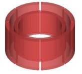
For example, this is the kind of arc segment I had in mind:
And below is the arrangement I had in mind, though with the magnets I first found the VC would be limited to less than 2". I'm sure other arc segments are available or could be manufacutured.
Why are magnets polarized N/S on their faces (assuming a ring shaped magnet, as is typically used in speakers, and even in the Parthenon) used in combination with ferromagnetic metal to complete the magnetic circuit on either side of the gap? In particular, why is the pole piece just ferrormagnetic metal? Why not magnetic material?
There are NeFeB magnets that are arc shaped, polarized N/S on their curved faces. If these were used to assemble two complete (near complete, anyway) rings to produce a gap - one ring outside the VC, and the other inside the VC where the pole piece typically is - would that not significantly increase the flux density? The motor structure could then be machined out of aluminum or other non-magnetic material.
For example, this is the kind of arc segment I had in mind:
An externally hosted image should be here but it was not working when we last tested it.
And below is the arrangement I had in mind, though with the magnets I first found the VC would be limited to less than 2". I'm sure other arc segments are available or could be manufacutured.
Attachments
I think Seas pretty much does this in some of their drivers-especially the new polyethelene cone midrange
EDIT Whoops, they use flat magnets and a small pole piece:
http://www.seas.no/about_seas___part_1.htm
EDIT Whoops, they use flat magnets and a small pole piece:
http://www.seas.no/about_seas___part_1.htm
That kind of approach is what Aura does - Neo as the face of the motor. Seas uses a similar type thing, but puts the magnets on the base of a standard pole, then uses straight up "faces" to carry to the outside of the gap.
The reason it's not done much is because of cost. Neo is expensive, and sintering it to the proper curve is very expensive (lots of cracks in production). Then when you magnetize it, you run an even greater risk of it exploding from a non-continuous force across the magnet. Bottom line - it's a very expensive way to build things.
Most neo motors have the neo disc at the base of the pole, then a pole "cap" on top of the magnet to create the inner side of the gap. Then you use a magnetic cup to carry the backside flux of the magnet to the outside of the gap. Single flat disc, easier to produce and charge, and close to a standard buildup. Can also be magnetized in a standard magnetizer (the radial units shown above are much more difficult to magnetize in an assembled motor).
Dan Wiggins
Adire Audio
RH,
Yes, you will get some flux to flow between naked magnets, but it'd be a great deal less than you'd see in the same case with a return circuit. Dunno...maybe I'll model it one of these days and see. It would be nice if it could be made to work...
...and if NdFeB was free.
Going a little OT here, but there are many nice things to be said about lining a VC motor gap with NdFeB (I think Aura holds the patent). You can set up some sweet underhung topologies, and you reap the benefit of NdFeB's high electrical impedance--you largely eliminate eddy currents and hysteresis distortion, much as ATC does with their proprietary SLMM (Super Linear Magnetic Material).
Some day, I want to build and measure a combination of Aura's and HyperDynamics' technology...
To machine or CNC machine thatis the question.
Mr. Wiggins I'm a guessing you never expect the parthenon to become a big seller.
Off shore manufacturing could be done. But the number of parts that such a shop would want to create would be prohibitive.
Stamping them out on a forge is also expensive considering the tooling costs. THis design is destined to become a rolls royce type product. Good but requires allot of effort.
Nice to see the posts on the motor. Keep them coming!!
MArk
Motor design fundamentals
RH, to add to Bill's comment...
The first image shows how two naked neo mags result in non linear flux across the gap. The second illustrates what happens when some ferromagnetic metal (trapezoid) is used to concentrate the flux into a small gap = increased flux density and increased linearity across gap. Also a standard return circuit provides a path connecting the poles, thus reducing stray fields and requiring less magnets.
Attachments
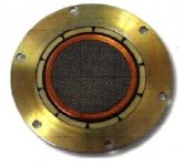
Aura Motor
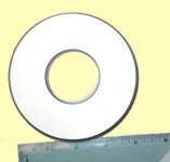
RHosch's last post of concentric arc'ed NdFeB is similar to the magnetic bearing in my push-pull motor sketch. For a bearing, the inner magnet would be much longer.
This image is the Aura Neo Radial Magnetic motor. The center cylinder is the steel pole piece that runs down and is attached to the outer cylinder-ring for the complete magnetic circuit. The next concencentric ring is a copper Faraday ring to reduce inductance. The ten arc segments outside the gap are the NdFeB magnets. NdFeB is brittle and difficult to machine. It would be difficult to manufacture an NdFeB ring to tight tolerances, and hence multiple arc segments are used. This topology offers a very uniform magnetic field over a long underhung coil length. The physical former and coil can be shorter than the JBL Differential Drive, and this can save mass. Also, the radial field and having only one magnet to metal interface gives good efficiency and field uniformity.
Seas Millenium tweeter uses a similar radial design with 6 rectangular bar magnets.
Attachments
Good to know I'm not unnaturally crazy. 🙂 Driver magnetic design is definitely not my specialty... the moving bits I do good with though. 😀
LineSource posted:
In fact, the Aura system has a few significant disadvantages as compared to a standard underhung approach (such as used by TC Sounds on the old Audiomobile MASS motors), the most obvious being lower thermal capability. Neo starts to degrade in terms of strength around 65 deg C (you can get neo which is good to 80 deg C now, though). Heat buildup in a neo motor is a serious concern - not only do you start to lose strength, but take it over its Curie temperature (which for most early formulations of neo was down below 110 deg C) and you permanently lose the strength.
Standard underhung (Aura) or overhung (most everyone else) topologies are a significant step behing the JBL Differential Drive (invented by HyperDynamics, and manufactured under license) in several ways, the most obvious being flux utilization. The Differential Drive (DD) approach uses the flux twice, rather than once. And while the total flux in the system is reduced (because of the presence of two gaps), because it's utilized twice you do get a net gain.
Another advantage of the multiple gap solutions is in terms of flux compression. Variation of total dynamic force in the system is greatly reduced, especially with the DD approach. As more current is poured into the motor, the voice coil's own field starts to cancel a significant portion of the motor's field, resulting in flux compression. A design like DD has the voice coils counter wound, meaning they inherently add as much as they subtract.
Multiple gap solutions also benefit from typically lower inductance for a given unit of stroke. In the case of XBL^2, you have a short voice coil to lower inductance. It's not as short as an underhung, but it does have considerably more stroke, and is more flux-efficient per turn as well, meaning fewer turns required to gain a given level of stroke and/or flux. In the case of the DD approach, you have counter-wound voice coils which also significantly reduce inductance. You gain a lot of the benefits of low inductance without using copper to get you there.
Lastly, underhungs suffer from serious thermal stability - power compression is a big issue without a LOT of custom work to solve it. Short voice coils aren't conducive to heat dissipation (and often the voice coils are very wide to get decent BL, like the 8 layer units in the Audiomobile MASS. This means once they heat up, they stay hot). Going with more surface area, while problematic from a motor size standpoint, is a good thing thermally. And if you equalize the number of turns, inductance and mass will stay the same. Ideally you want your voice coil to have as much surface area as possible - underhungs force you to do otherwise.
The Aura motor is quite unique, and does result in about the most compact motor you could ask for; however, I'd rather go with a big neo slug at the base of the pole and use a standard neo approach. Big round discs of neo are readily available, and a lot easier to make than the curved arcs of neo in the Aura (which, to the best of my knowledge, are only available from a single source in Russia).
Dan Wiggins
Adire Audio
No more so than a standard underhung approach with a ceramic magnet on the outside. The only unique thing about the Aura is the use of neo radial pieces, to make the motor physically quite compact. But to get a given Xmax with a given gap height, you use the same size voice coil as you would for an underhung unit.This topology offers a very uniform magnetic field over a long underhung coil length. The physical former and coil can be shorter than the JBL Differential Drive, and this can save mass.
In fact, the Aura system has a few significant disadvantages as compared to a standard underhung approach (such as used by TC Sounds on the old Audiomobile MASS motors), the most obvious being lower thermal capability. Neo starts to degrade in terms of strength around 65 deg C (you can get neo which is good to 80 deg C now, though). Heat buildup in a neo motor is a serious concern - not only do you start to lose strength, but take it over its Curie temperature (which for most early formulations of neo was down below 110 deg C) and you permanently lose the strength.
Standard underhung (Aura) or overhung (most everyone else) topologies are a significant step behing the JBL Differential Drive (invented by HyperDynamics, and manufactured under license) in several ways, the most obvious being flux utilization. The Differential Drive (DD) approach uses the flux twice, rather than once. And while the total flux in the system is reduced (because of the presence of two gaps), because it's utilized twice you do get a net gain.
Another advantage of the multiple gap solutions is in terms of flux compression. Variation of total dynamic force in the system is greatly reduced, especially with the DD approach. As more current is poured into the motor, the voice coil's own field starts to cancel a significant portion of the motor's field, resulting in flux compression. A design like DD has the voice coils counter wound, meaning they inherently add as much as they subtract.
Multiple gap solutions also benefit from typically lower inductance for a given unit of stroke. In the case of XBL^2, you have a short voice coil to lower inductance. It's not as short as an underhung, but it does have considerably more stroke, and is more flux-efficient per turn as well, meaning fewer turns required to gain a given level of stroke and/or flux. In the case of the DD approach, you have counter-wound voice coils which also significantly reduce inductance. You gain a lot of the benefits of low inductance without using copper to get you there.
Lastly, underhungs suffer from serious thermal stability - power compression is a big issue without a LOT of custom work to solve it. Short voice coils aren't conducive to heat dissipation (and often the voice coils are very wide to get decent BL, like the 8 layer units in the Audiomobile MASS. This means once they heat up, they stay hot). Going with more surface area, while problematic from a motor size standpoint, is a good thing thermally. And if you equalize the number of turns, inductance and mass will stay the same. Ideally you want your voice coil to have as much surface area as possible - underhungs force you to do otherwise.
The Aura motor is quite unique, and does result in about the most compact motor you could ask for; however, I'd rather go with a big neo slug at the base of the pole and use a standard neo approach. Big round discs of neo are readily available, and a lot easier to make than the curved arcs of neo in the Aura (which, to the best of my knowledge, are only available from a single source in Russia).
Dan Wiggins
Adire Audio
I'd rather go with a big neo slug at the base of the pole and use a standard neo approach. Big round discs of neo are readily available,
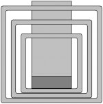
...An excellent segue to my first back o' the napkin sketch of how we might save money on the motor structure.
Remember how they used to do AlNiCo motors with a section of square tubing serving as the return circuit? This is the same concept to the 3rd degree.
The picture below is a side view of a tri-gap motor composed of a 4" dia. cylindrical pole, a 4" dia. puck of NdFeB (available on Ebay! 🙂) at the base of the pole, and three nested sections of square structural steel tubing, (available, perhaps, at your local salvage yard).
This design would cut way down on both material and machining costs. Properly executed, this circuit could have all the functionality of the Partheon motor, with none of its beauty. 😉
There is also the possibility of a Parthenonesque design compromise that would use square plates and pillars which would be cheaper than the Parthenon's cylindrical machinings.
Attachments
What about using a 4.25" ring magnet, like the one at the bottom of this page:
http://www.engconcepts.net/Magnets/Pages/Ring_Magnets.htm
--
Brian
http://www.engconcepts.net/Magnets/Pages/Ring_Magnets.htm
--
Brian
Attachments
- Status
- Not open for further replies.
- Home
- Loudspeakers
- Subwoofers
- DIY Parthenon