Also, on the subject of the basket and chassis...
Note on this Resonant Engineering XMX sub (that black motor is a different implementation of similar XBL^2 geometry, using a bigger single Neodymium disk), they used the sweep surfaces I was talking about, and a simple welded tubular steel frame for a chassis.
Welding up a frame like that would not cost much.
I don't think that machining the copper springs to construct our own "Arachnid" spider would be too cost prohibitive either.
Note, in this pic, the RE rep was pushing the cone assembly up as far as it would go, you can see the suspension isn't even bottomed out. They also used a 'guide-rod' type assembly to keep things moving linearly:
I'm guessing we'd want our finished product to look a bit like that?😕
My alteration would be to get rid of the guide-rod strategy, simply extend the former through the cone assembly (or attach another one), and hang another "arachnid" style spider on the top of that part of the frame, in addition to the one like they have attached to the bottom of the frame.
Could simplify tinsel management too... the whole top set of springs could be "positive", while the whole bottom set could be "negative" (or vice versa) 😎
Hopefully those pics help.
Note on this Resonant Engineering XMX sub (that black motor is a different implementation of similar XBL^2 geometry, using a bigger single Neodymium disk), they used the sweep surfaces I was talking about, and a simple welded tubular steel frame for a chassis.
Welding up a frame like that would not cost much.
I don't think that machining the copper springs to construct our own "Arachnid" spider would be too cost prohibitive either.
Note, in this pic, the RE rep was pushing the cone assembly up as far as it would go, you can see the suspension isn't even bottomed out. They also used a 'guide-rod' type assembly to keep things moving linearly:
An externally hosted image should be here but it was not working when we last tested it.
I'm guessing we'd want our finished product to look a bit like that?😕
My alteration would be to get rid of the guide-rod strategy, simply extend the former through the cone assembly (or attach another one), and hang another "arachnid" style spider on the top of that part of the frame, in addition to the one like they have attached to the bottom of the frame.
Could simplify tinsel management too... the whole top set of springs could be "positive", while the whole bottom set could be "negative" (or vice versa) 😎
Hopefully those pics help.
Now we are getting some gooood spy stuff!!!!!
OK these pics are worth their weight in ferro fluid! At least!
They give more ffod for thought. Was this driver playing??
What kind of power was used to get it a moovin? And is that 1/2" melamine used as a baffle????
RHosch has some ideas going that make some sense but I take issue with no basket no surround.
Maybe no surround is practical. But no surround is asking for big trouble. Just think about a diaphram what ever it is made from rapidly oscillating over a stroke of almost seven inches. Imagine being smacked by it!! Imagine your kid, wife or whatever being smacked by it and you might want a basket.
A surround is only needed if we want to construct a pressure transducer ( in a box )
Those springs are neat. They form one idea as to how to create a controlled excursion and return force.
They could probably be wound from music wire just as well. IF we did a good web search we may even find something similar.
No body designs in a vacuum!
As for linear stroke they used an over extended pole piece and a delrin bushing as a support?????
And it knocked about??
Well shoot the machinist. Maybe it wasn't quite ready to be sent out into the world yet.
I have a couple of blocks of teflon about an 1 1/2" thick I guess they could do if it was needed. But I still like the frelon bushing on a ground a polished shaft of mild steel. It probably will provide less friction as well!
I agree with RHosh about there not being more friction when you have a larger ideal shaft surface. But in the real world it is harder to align multiple shafts. Especially when we are trying to make a design that is DIY friendly. If I had to make a multiple shaft design I would float them in a oversized hole and then tweak them untill there was least friction. But one larger shaft will probably work just as well. Reducing torque is going to be acomplished by the suspension system more than the linear bearing.
So any comments on the sound???
Power??
To basket or not to basket???
MArk
Re: Now we are getting some gooood spy stuff!!!!!
Dan Wiggins commented to me that the machining wasn't quite to spec on the Delrin guide rod/carrier, so it chattered when in use on actual music.
But he was demoing it with a 9v battery, and it was able to reach nearly full excursion with just that...
...one reason I say I suspect the copper springs to possibly not be stiff enough. 😉
Reference the Resonant Engineering XMX sub...
...that is exactly what I was originally suggesting that we do (check my post from the 8th 😎 )
No surround, a diaphragm that swept against a set of walls similar to how a car piston sweeps the cylinder in an engine block.
Cheap, easy, long excursion capable, without limitation. 😎
I don't think music strings would provide enough restoring force...
I don't think that spider as-is would, in fact.
Dan says it would though, and I'd trust his word over my intuition at any rate. 😀
And this is just a one-off prototype, it's not ready for the world yet. No chassis or anything on that bad boy.
But it's also more machinable than Teflon, and it definitely holds it's shape better over time.
I'm not a fan of the whole guide-rod approach though...
I'd rather build a chassis like the XMX (which wouldn't be expensive), with walls for the sub to sweep against (which would allow for either free-air, enclosed, or dipole use), with a spider both above and below the diaphragm... simply connected to the chassis at both the upper frame and lower frame...
Picture the XMX sub with another "former" if you will coming off the front of the cone, with another Arachnid spider attached to it, and the top of the chassis, just like the Arachnid spider attached to the bottom of the chassis.
That would eliminate the need for the guide-rod assembly, eliminating any friction, while also providing lower compliance without requiring prohibitively expensive thick copper for the springs. 😎
Seems like a lot of maintenance to boot. 🙁

I'm definitely a fan of building a chassis similar to that XMX, which would allow for any use... enclosed, free-air, or dipole.
Anyone ever considered that a servo motor truly has an infinitely flat BL curve? And that it's got about 10x the efficiency of a voice coil motor?
Ok, that'll be enough of that...
(I don't think we could find a servo-motor large enough anyway 😉 )
😀
It was playing, not while I was there, I suspect not at CES at all.mwmkravchenko said:Was this driver playing??
What kind of power was used to get it a moovin? And is that 1/2" melamine used as a baffle????
Dan Wiggins commented to me that the machining wasn't quite to spec on the Delrin guide rod/carrier, so it chattered when in use on actual music.
But he was demoing it with a 9v battery, and it was able to reach nearly full excursion with just that...
...one reason I say I suspect the copper springs to possibly not be stiff enough. 😉
We still don't need a surround.RHosch has some ideas going that make some sense but I take issue with no basket no surround.
Maybe no surround is practical. But no surround is asking for big trouble. Just think about a diaphram what ever it is made from rapidly oscillating over a stroke of almost seven inches. Imagine being smacked by it!! Imagine your kid, wife or whatever being smacked by it and you might want a basket.
A surround is only needed if we want to construct a pressure transducer ( in a box )
Reference the Resonant Engineering XMX sub...
...that is exactly what I was originally suggesting that we do (check my post from the 8th 😎 )
No surround, a diaphragm that swept against a set of walls similar to how a car piston sweeps the cylinder in an engine block.
Cheap, easy, long excursion capable, without limitation. 😎
And they'd be cheap to machine.
Those springs are neat. They form one idea as to how to create a controlled excursion and return force.
I don't think music strings would provide enough restoring force...
I don't think that spider as-is would, in fact.
Dan says it would though, and I'd trust his word over my intuition at any rate. 😀
Essentially, yes... not an extended pole piece per se... the extension was made of Delrin also. 😉As for linear stroke they used an over extended pole piece and a delrin bushing as a support?????
And it knocked about??
Well shoot the machinist. Maybe it wasn't quite ready to be sent out into the world yet.
And this is just a one-off prototype, it's not ready for the world yet. No chassis or anything on that bad boy.
Delrin is actually slipperier than Teflon, even, I believe.. one reason for it's high price tag.I have a couple of blocks of teflon about an 1 1/2" thick I guess they could do if it was needed. But I still like the frelon bushing on a ground a polished shaft of mild steel. It probably will provide less friction as well!
But it's also more machinable than Teflon, and it definitely holds it's shape better over time.
I'm not a fan of the whole guide-rod approach though...
I'd rather build a chassis like the XMX (which wouldn't be expensive), with walls for the sub to sweep against (which would allow for either free-air, enclosed, or dipole use), with a spider both above and below the diaphragm... simply connected to the chassis at both the upper frame and lower frame...
Picture the XMX sub with another "former" if you will coming off the front of the cone, with another Arachnid spider attached to it, and the top of the chassis, just like the Arachnid spider attached to the bottom of the chassis.
That would eliminate the need for the guide-rod assembly, eliminating any friction, while also providing lower compliance without requiring prohibitively expensive thick copper for the springs. 😎
Well, Dan was commenting that there was a special wax that they needed to use to treat the guide-rod assembly...
I agree with RHosh about there not being more friction when you have a larger ideal shaft surface. But in the real world it is harder to align multiple shafts. Especially when we are trying to make a design that is DIY friendly. If I had to make a multiple shaft design I would float them in a oversized hole and then tweak them untill there was least friction. But one larger shaft will probably work just as well. Reducing torque is going to be acomplished by the suspension system more than the linear bearing.
Seems like a lot of maintenance to boot. 🙁
No comments on the sound, unfortunately, or required power... the latter is definitely more the mystery.
So any comments on the sound???
Power??
To basket or not to basket???
MArk
I'm definitely a fan of building a chassis similar to that XMX, which would allow for any use... enclosed, free-air, or dipole.
Anyone ever considered that a servo motor truly has an infinitely flat BL curve? And that it's got about 10x the efficiency of a voice coil motor?
Ok, that'll be enough of that...
(I don't think we could find a servo-motor large enough anyway 😉 )
😀
Of stolen pics and great ideas....
Cool stuff in the making here. We have a basis for a lot of tinkering on the mechanical side of things. Now we need some words of wisdom from our motor guru!!! Bill where are you????
WE could bring together a changeable mechanical assembly. But all is for nought if we don't have a motor to drive it.
Mark
I'm going to use my XBL^2 software (Adire Audio's modeling software) to see if I can model up a few different versions...
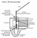
One curiosity I have is to see if I can determine why Adire decided to use the dual-gap, dual-staggered-coil approach to acheive 80mm, as opposed to using a single coil traversing three or maybe four gaps to do so.
My initial guess is simply cost...
More gaps, more magnets, more money.
One curiosity I have is to see if I can determine why Adire decided to use the dual-gap, dual-staggered-coil approach to acheive 80mm, as opposed to using a single coil traversing three or maybe four gaps to do so.
My initial guess is simply cost...
More gaps, more magnets, more money.
a little bit OT
tomorrow's New York Times "Arts and Leisure" section will carry an article on the new Parthenon. (we get Saturday delivery of the A&L).
tomorrow's New York Times "Arts and Leisure" section will carry an article on the new Parthenon. (we get Saturday delivery of the A&L).
PUSH - PULL MOTORS
How about a PUSH - PULL design with the diaphram between two motors?
No suspension for restoring force would be necessary, each motor could be half the power, distortion would be lower due to even push-pull forces and canceling non-linearities between the motors.
I think a magnetic bearing would also be easier to design around a push-pull topology. Circular arcs of NdFeB magnets are available. One long circular arc'ed magnet between the two motors for the inner bearing, and a larger diameter circular arc'ed magnet attached to the center of the diaphram - long enough to provide enough leverage to stop angular diaphram movement.
I would also build the push-pull JBL Differential Drive motor with front and rear spiders Very low distortion, very low Le.
Attachments
Member
Joined 2002
Who ever need's Pictures hosted for any reason please email me you can host them on m site / gallery just like otehr users on the form.. Free OF charge.. : O)
Jason..
Jason..
Any questions, I'll answer to the best of my ability...🙂
Dan Wiggins
Adire Audio
"The Parthenon Guy"
Dan Wiggins
Adire Audio
"The Parthenon Guy"
Models and other ugly ducklings
Now we are talking!!!!!!!!
We get to model a motor. 😎 😎 😎 😎 😎 😎
I'm not pretending that the mechanical design is all said and done. But there is enough of an idea to get it off the ground. If we have a functional motor structure then we are only trying how to harness it with the least amount of losses and the greatest amount of control.
To get back to some real world metal working there must be an understanding that getting 1010 steel is not easy. If we are lucky I can get 1015 locally. This basically means that we will not have as strong a motor as we would like. The differences are not huge but they are there. I'm not going to pop for the silicone iron for a prototype unless someone richer than me wants to pay for it!!
The pole piece is one part that may be made out of a heavy wall tubing instead of a turned and bored piece. I'll look around when we get more serious. Geolemon make sure that you model the correct amount of iron in this simulation. We may need to talk it over a bit. As for voice coils we could get three off the shelf 100mm types. There are houses that do custom winding and there are even the big boys that smple. I remember doing some work with Aton a long time ago. I may still have some of their data books. Would save a whole lot of time. It's a big pain to wind voice coils and if we still want to the K.I.S.S. principle to reign it makes the most sense.
The multiple gaps that geolemon wrote about are probably on the money. Namely it is cheaper to hake a two gap product then a three. And yes it means less magnets = less cost. As a manufacturer you cannot hope to get them at surplus prices for any length of time. So their cost is a significant part of the cost of a driver. Also the more machining that you put into a motor structure the more it costs.
Magnetic bearing idea is still in my head. I was just at the place to get the magnets and I forgot all about it.🙄
I promise to remember sometime soon.
It would be cool if we could generate a stable lateral force on a magnetic tube. It is not that practical to expect a linear dampening effect as well, but who knows. If it works wow we are going to have some fun. True magnetic suspension!!!!
Back to the laboratory ( getting to carried away ( or should be ))
Mark
Push-pull Motor
How about a PUSH - PULL design with the diaphram between two motors?
No suspension for restoring force would be necessary, each motor could be half the power, distortion would be lower due to even push-pull forces and canceling non-linearities between the motors.
I think a magnetic bearing would also be easier to design around a push-pull topology. Circular arcs of NdFeB magnets are available. One long circular arc'ed magnet between the two motors for the inner bearing, and a larger diameter circular arc'ed magnet attached to the center of the diaphram - long enough to provide enough leverage to stop angular diaphram movement.
I would also build the push-pull JBL Differential Drive motor with front and rear spiders Very low distortion, very low Le.
Attachments
The man is here??????
Mr. Dan Wiggins. My only question is how close are we getting???? And do you want to reveal all?? ( your design ideas in principle not exact specifics )
Mr. Linesource I like the idea. It will cost twice as much. Weigh twice as much. Will we get a double benefit in canceled even order distorsion??? And will your magnetic bearing idea work???
Can you give a bit of an explanation?? For the bearing. The rest makes sense.
Mark
You're plenty close - it's a pretty standard buildup - one motor, one suspension - that we used, just used some of our patent pending approaches for the motor and suspension.
What kind of details do you want? One thing to be aware of with the dual gaps in opposite flux polarity, it is patented by HyperDynamics, and used in multiple licensed models. Building a patented product - even for educational/instructional purposes - is illegal. As such, I'd recommend not using the approach shown in LineSource's post.
When the patent issues for our XBL^2 motor approach, I will waive prosecuting patent infringement for non-commercial applications related to this thread. So it's a "safe" way to go here...🙂
With that said, note that even/odd distortion from motors is related to BL nonlinearities over excursion. A flat BL motor like the XBL^2 approach makes using a push/pull arrangement essentially irrelevant.
Magnetic bearings can work, but they need to be pretty far out from the motor itself. Note that if the voice coil moves over the magnetic bearing (or even gets close to it) the BL of the driver will change. You can't have your magnetic bearing near the motor parts. And with high stroke, that means you need to be quite a way from the center of the driver. Thus the reason we chose the simpler approach of a slip ring. Properly machined, it's close enough to eliminate chatter, and once waxed (only need to do every thousand hours of operation or so) it is remarkably silent.
Front and rear spiders as Chris (Geolemon) espouses also works, but you'll still want a guide of some sort. We used the lightest materials we could find, and still had an Mms of 800 grams. to work with spiders, you'd have to have a decent stiffness, which would raise the Fs and Qts of the driver. So, to keep Fs down to the single digit range, we used a really soft spider setup, and the mechanical bearing for support. Note that efficiency is strictly BL and Mms, so keeping Mms down was imperative for us (efficiency of the Parthenon as is clocks in around 97 dB @ 1W, 1m, thus the reason it jumps 2.5" one way with a 9V battery).
Triple gaps work, as do quad gaps, 5 gap, etc. Simply increases the cost and complexity of the motor. And the diameters of the plates start to get big, unless we play some fun games with dual gap plates hung off of each row of columns. Simpler way to do this is to use dual or triple gaps, and dual voice coils. Many supply houses will do small runs of voice coils custom wound - not cheap, but doable.
Any other questions, just ask!
Dan Wiggins
Adire Audio
DanWiggins said:Building a patented product - even for educational/instructional purposes - is illegal. As such, I'd recommend not using the approach shown in LineSource's post.
Hmm, unless the patent law is different in the states youre wrong. I know for a fact that in europe it is leagal to produce a patented product. The only thing a patent does, is that it makes the holder of the patent the only one allowed to sell the ithem. So as long as you dont sell anything....youre free to use any patent you feel like using.
This statement is based on a case my father went to court with.
It is 100% sure that its correct, since if it wasnt he would have been fried by the crowd of lawayers the company that sued him showed up with.
The actual case was that he made prototypes of a product soon to be free of patent (25 years old) half a year before it was free. The verdict was that he was allowed to make as many as he pleased....he could even give them away for free....as long as he didnt sell them.
Cheers
Magura
Hi Guys,
Sorry I've been a bit of a stranger recently. Work had me hoppin'. Looks like you guys are doing just fine without me anyway. 😀
😀
Dan,
Gotta say it again here--I really deeply appreciate your openness and accessibility to the DIY zoo. Just considering the time involved, you're making no small investment in us. And your liberality with your technology sets the (transducer) industry standard, IMHO, much as Mr. Pass has done on the electronics end of things. I truly hope it pays off for you!
Hats off to you, sir!
Sorry I've been a bit of a stranger recently. Work had me hoppin'. Looks like you guys are doing just fine without me anyway.
😀 Dan,
Gotta say it again here--I really deeply appreciate your openness and accessibility to the DIY zoo. Just considering the time involved, you're making no small investment in us. And your liberality with your technology sets the (transducer) industry standard, IMHO, much as Mr. Pass has done on the electronics end of things. I truly hope it pays off for you!
Hats off to you, sir!
Magura,
In the US, any implementation of a patented object is subject to prosecution - commercial or otherwise. Best to always get explicit approval for implementation even for personal use/educational reasons.
Bill,
My pleasure! I take great inspiration from the DIY market... A lot of what we've been doing is driven by the desire of the extreme high end (which I classify as DIYers, not the typical high end companies) for better performance.
Dan Wiggins
Adire Audio
Now I can understand preventing commercial implementation, but this just takes the biscuit. I must cry human rights violation. 'Someone else has done it first so I'm not allowed to'. I'm sorry, but no! Take me to jail if you must. I'll take em all on.any implementation of a patented object is subject to prosecution - commercial or otherwise

Those pics of the Parthenon at CES are awesome, as is the progress in this thread. It shaping up into something special. The boxroom's not being used, perhaps a potential enclosure for this monster then...

We need a motor!!!
Given our ingenious group of mechanical and seat of the pants engineers we probably have a working ( with allot of tweaking ) mechanical sytem. At least there are enough ideas to get it off the ground. The large pics posted on the parthenon pic thread are Oh so Good!! Those progressive springs are really the cats meow!! A pat on the back of whoever came up with that. Out with the spiders and in with the springs. Just a guess but are we talking bronze here???? Silicone bronze could work if it is half hard. Any thoughts or ones who know would you let us in on the secret??? ( Dan you know who I'm talking to 😀 ) I'm thinking of how to setup a simple as possible jig to bend them. Number 12 guage music wire (not for musical instruments hardened and tempered for making springs) might be the ticket. It might be easier to cut them out of a sheet with a power scroll saw!
SO WHERE IS THE MOTOR??????
I do not have the programs to simulate a descent motor design. And more to the point I'm six years rusty and there are just to many other things to attend to. I'll be having my hands full on a prototype mechanical construction.!!
The magnetic bearing will change the Le and the Bl of the coils. Not something you want!
We want a stable as possible Bl and as stable as possible Le. Sapping motor strength and having a variable inductance is plain nuts. More potential sources for IM distorsion are not what a moving coil transducer needs. A good motor design has enough problems to begin with. This design seems to minimise some of them by allowing a flatter Bl curve. Thus the purpose of multiple gaps.
More questions for Dan.
What grade of steel did you use?
Why no cone?
And is that really 1/2" melamine??? Must be heavy.
Does the driver sound good??
WHat sound pressure do you really get at 2 to 3 metres?? ( I've done the theoretical calcs but they are only that a Big idea )
I'm guessing that you were going for a near piston fit and using the wax as a phase change lubricant. Good idea to.
But couldn't you have done a thin wall aluminum tubing for the diaphram sleeve ( seamless tubing comes to mind ) and an extended guide off the pole piece?? might have been lighter. I have to find out the weight of delrin. ( It's about half the weight of aluminum. The web is a wonderfull thing when you forget. But not as strong )
Enough babling. Up to our intrepid motor designers to push us farther.
Mark
Spider pieces were waterjet cut from Beryllium Copper. There's lots of good metals to use, including spring steel, which is widely and cheaply available (if not as pretty as BeCu).
Steel is 1008 grade - expensive stuff to get. Grades 1010 or 12L14 would also work.
The flat diaphragm is the cone - no cone needed. This design was for the ultimate dipole sub, so we just needed a bit rigid panel moving back and forth. So a flat 24" square baffle was the easiest, lowest moving mass way to do it.
The diaphragm is a custom composite of woven fiber and balsa wood, epoxy treated. Total moving mass - including the former, voice coils, former-cone attachment, etc. - is 800 grams. Pretty light, all things considered.
The driver sounds fine, if you ignore the rocking we have from the loose spacing now. Once tightened up, it'll sound fine. Just need a bit of dipole EQ to keep the frequency flat.
SPL at 2 meters is pretty stupid... On the order of 110 dB anechoic, at 20 Hz. Wicked levels of output. In a typical room, and with the output cranked to the full excursion limits, I'd expect over 120 dB SPL @ 2 meters from ~20 Hz and up.
The piston idea of the diaphragm core is correct - a tight fit of slippery plastics with a bit of dry lube works wonders. VERY low friction. Metal on metal (particularly aluminum on aluminum) has a VERY high static friction. You need a good amount of force to get things moving before you reach the low dynamic friction levels. A high static friction creates "stiction", which is akin to a class B amp with crossover glitches. So we chose materials that gave a low static friction, and even lower dynamic friction.
So, what does everyone want for the motor? Fewer parts are easier/cheaper - going with 3 or more gaps gets expensive. Try tracking down a 12" square of 1" thick 1008 grade steel and you'll understand why these things are so expensive...🙂
Note too that the larger the diameter of plates, the more expensive the machining becomes. We hold all our plates to less than 0.007" runout over the entire diameter. That gets VERY expensive for large diameters, because the grind/cut must be super flat. You can't just use stock 3/4" material and get that kind of flatness - you need to start with thicker material and cut down.
Dan Wiggins
Adire Audio
Beatifull body but got no motor
Oky doky
Appreciation on the posting. For a motor lets go for broke. What would Dan Wiggins do if he had no cost contraints. The steel is not free but not extremly costly. I believe that I can get a suitable supply of neo magnets at a reasonable cost as well. So lets go for it!
Reallity check is this.
1008 steel is expensive in North America because nobody wants it. Sticky stuff to machine and it's physical properties sick. ( alltough it's good for magnetic circuits.
1010 is more common. It will not achieve as great a flux density but thems the breaks.
Yep I'd machine down 1" plate to get to the reqired thickness. .007 TIR is not easy but is not impossible. And it is not needed in all the ares either! The interior bore is probadly the most critical area ( where the voice coil goes inbetween the top plate gaps and the pole piece. I'm guessing that you used a "T" shape at the pole piece top plate junctions to properly focus the flux. Are there any farady rings and the like in this design?
If this thing actually works ( motor ) I'd consider casting it in sections from grey iron. Not the ideal iron but a better than common mild steel. It would give me a good excuse to finnish that foundry I've been working on🙂 Come to think of it if a good protection basket comes out of the works it can be cast in aluminum to. Thinking thinking and still no head ache. Must be onto something.
Mark
- Status
- Not open for further replies.
- Home
- Loudspeakers
- Subwoofers
- DIY Parthenon