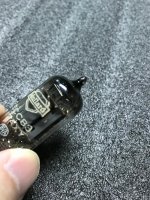
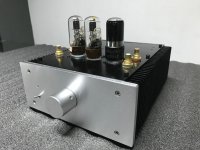
This is a modified Marantz M7 circuit design using 6SN7 and 6SL7, but still can use ECC83. What makes this circuit so special is the use of DB3 at output, so what's the use of that? I will let you all guess😀
Attachments
-
M7 Power.pdf13.5 KB · Views: 295
-
 a5ef2327-3d6e-4f07-80a0-725b32f9d290.jpg126.4 KB · Views: 463
 -
 ccd9a2dd-f81d-4a7f-bb91-b4c5603d3c1c.jpg118.5 KB · Views: 362
 -
 75600514-390b-4107-8d0a-8293fbe5a667.jpg124.8 KB · Views: 369
 -
 d3946125-b96c-4dcc-a5b6-e7e620d673a0.jpg188 KB · Views: 934
 -
 f809f4a8-7eb9-4242-9bc8-55f18a77037e.jpg163 KB · Views: 920
 -
 489b8fcf-1506-439d-ae44-c5ceab624158.jpg112.9 KB · Views: 929
 -
 4dbef2a3-ca2d-411a-9c57-fbf05ddb4c69.jpg106.6 KB · Views: 953
 -
 3ce49834-d5be-4df5-9f1f-161f4e5373ca.jpg107.3 KB · Views: 954
 -
M7.pdf15.2 KB · Views: 387
What's a Marantz M7?
As far as I know the only model 7 preamps Marantz made were the 7C (tube) and the 7T (SS). The 7C used all (5) 12AX7s. What's the connection to Marantz?
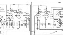
Here's a section of the 7C schematic. I'm not very technically oriented but it doesn't look the same to me.
As far as I know the only model 7 preamps Marantz made were the 7C (tube) and the 7T (SS). The 7C used all (5) 12AX7s. What's the connection to Marantz?
Here's a section of the 7C schematic. I'm not very technically oriented but it doesn't look the same to me.
Attachments
What makes this circuit so special is the use of DB3 at output, so what's the use of that? I will let you all guess😀
I guess you’re expecting the output capacitor to fail at some point? It hardly makes it special in any way.
What's a Marantz M7?
As far as I know the only model 7 preamps Marantz made were the 7C (tube) and the 7T (SS). The 7C used all (5) 12AX7s. What's the connection to Marantz?
Here's a section of the 7C schematic. I'm not very technically oriented but it doesn't look the same to me.
I guess our newest member is from the oriental land, citizens of planet audio in that part of the world is still raving about the Marantz model 7c or "M7" as they call it. The model 7C and the model 9B power amp still command some handsome money in the second hand market. They seem to really enjoy that mellow mid range of the said preamp. Many in the DIY community have gone all the trouble to "optimise" the circuit with difference tubes and resistor/capacitor value, whether the resulting circuit and tone has any resemblance to the original Marantz model 7C is questionable.
I built one using the a very similar circuit, 3 12ax7 and some cheap components, extremely high gain for modern power amp but mate wonderfully with big MOFO by Michael Rothacher which has no gain. I can understand why audiophile in Asia like it so much, the mid range is very sweet indeed one can almost tastes it.
When they say M7 circuit, they actually mean the output section of the model 7C without the RIAA and tone circuit. What you've posted is the the RIAA and the first 2 stages of the output section. Here is the full model 7C circuit:
Attachments
I know! I know! It lets you hook it up to a thyristor and then you can use the 7C volume knob to control industrial lighting and motor speed.What makes this circuit so special is the use of DB3 at output, so what's the use of that? I will let you all guess😀
The amps circuit is the same as the 7C.Here's a section of the 7C schematic.
Since i improved the power supply , input, output circuit & the output tube, it not exactly the 7C.
So i named it as M7. M is stand for Marantz.
the guessing is not correct. there have a more important usage.I guess you’re expecting the output capacitor to fail at some point? It hardly makes it special in any way.
take an other guess.
i will post the answer later.
what you mention is correct.I guess our newest member is from the oriental land, citizens of planet audio in that part of the world is still raving about the Marantz model 7c or "M7" as they call it.
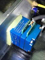
I improved the power supply , input, output circuit & the output tube, it not exactly the 7C. especially i have added a DB3 on the output.
The DB3 is not to control industrial lighting and motor speed.
The have another important function.
you will appreciate me when i announced the answer. 😀
The have another important function. you will appreciate me when i announced the answer. 😀
I took the rest of the year off from work and I am waiting by my computer with great anticipation. I am not even going to sleep. I am sure it will be a seminal moment in the history of electronics.
Can you give me a hint? Does it have anything to do with keeping rodents away?
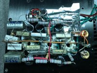
The wiring under the chassis looks like a fire that hasn't started!😱
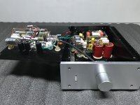
I like the way the stepped attenuator, the power switch and the power indicator are held in place with hot melt glue and chewing gum.
Please don’t leave it unattended when it’s powered up!
Last edited:
Of course I don't,we're all idiots here,eagerly waiting to be enlightened.Le Basseur, You know the answer?🙂
I might have,though,a slight hunch wich I'm not allowed to disclosure due to moral restraint issues.

In the meantime,let's see the real deal here as presented by the OP or his knowledgeable buddy...we're all still waiting 😉
I believe that AudioGANG posted here to get some CONSTRUCTIVE criticism, so I will post mine. By the way, I see good soldering skills, thought has been applied on the ground layout, and there is an attempt to shield the low level signal circuits. It is already a step above most beginner builds I've seen, and the preamp is probably working fine right now. Unfortunately, it will likely develop faults very soon due to the way it has been built. The biggest mistakes are: the lack of mechanical support to heawy parts, because glue and tape will eventually give way, the only remaining support will be the solder and components will move; and the tight random crossing of parts and wires. Power resistors could not be mounted beneath electrolytic capacitors, because the heat will degrade the capacitors. The Morgan Jones "Building Valve Amplifiers" book may be a good reading; maybe some members here could give to the OP further references to point to point best practices.
I took the rest of the year off from work and I am waiting by my computer with great anticipation. I am not even going to sleep. I am sure it will be a seminal moment in the history of electronics.
Can you give me a hint? Does it have anything to do with keeping rodents away?
Sure and I do have a hint. You may consider the capacity of C6 at the output from the M7 schematic. As you're not going to sleep, let me give you two more questions to think about, which will be posted later below.
The wiring under the chassis looks like a fire that hasn't started!😱
I'm sorry to say that this Marantz M7 was finished within one day, which is really in a rush. It may look a bit messy but it is definitely safe to use.
I like the way the stepped attenuator, the power switch and the power indicator are held in place with hot melt glue and chewing gum.
Please don’t leave it unattended when it’s powered up!
The high-voltage soldering points of LED and power switch were isolated by double heat shrink tubes, which is safe even the glue has lost. Thanks for your concern! In fact, the glue I used is in industrial application, to lose it you have to use an electric drill.
The reason why I held the stepped attenuator in place with hot melt glue is to avoid the attenuator from loose in position. For the LED and power switch, I hope to make my design appearance to be good from not using nuts, so I also used hot melt glue here instead of screw.
As you just mentioned the stepped attenuator, another question I would like to ask you all is why I used a shunt-type attenuator, but not a series-type nor a leader-type one? What are the benefits? Who knows the answer?😀
 Start over.
I believe that AudioGANG posted here to get some CONSTRUCTIVE criticism, so I will post mine. By the way, I see good soldering skills, thought has been applied on the ground layout, and there is an attempt to shield the low level signal circuits. It is already a step above most beginner builds I've seen, and the preamp is probably working fine right now. Unfortunately, it will likely develop faults very soon due to the way it has been built. The biggest mistakes are: the lack of mechanical support to heawy parts, because glue and tape will eventually give way, the only remaining support will be the solder and components will move; and the tight random crossing of parts and wires. Power resistors could not be mounted beneath electrolytic capacitors, because the heat will degrade the capacitors. The Morgan Jones "Building Valve Amplifiers" book may be a good reading; maybe some members here could give to the OP further references to point to point best practices.
First thing first, thank you so much for your kind criticism. The two biggest mistakes you mentioned, I've actually handled them with good considerations so I think there is no worry about them.
Talking about the lack of mechanical support, I've handled the components with double coiling on their soldering legs, so even the solder has lost you could still find the components are held in a place well.
For the mounting of power resistors beneath capacitors, according to simple capacitor decay theory, with every 1 Degree Celsius increase, the lifetime of a capacitor drops by 1 time. If you take a closer look on the power resistors and capacitors, which are actually 20mm away from each other. The power resistors could actually heat up the capacitor by at most 5 Degree Celsius, in other words, the effect towards capacitors is really small that only causes a small degrade. Also, the capacity of the capacitors I used here, is 10 times bigger than the original Marantz M7 design. Therefore, I'm pretty sure to say that the lifetime of my design will be much longer than the original one. You don't have to worry about it.
Somehow it's sadly to say that you've no idea about why I was handling my work in this way. In fact, these were trade-offs from minimizing the noise and audio path distance, as well as keeping the power supply damper ability as close as the amplifier, resulting this complicated circuit you all see here.
I guess you’re expecting the output capacitor to fail at some point? It hardly makes it special in any way.
You're very close to the answer. Good and try again 😎
So here I officially post the two more questions about this modified Marantz M7 design:
1. As observed from the two schematics I previously posted, why did I apply a voltage doubler rectifier circuit but not a bridge rectifier one?
2. Also, why did I apply a shunt-type attenuator in the circuit, instead of a series-type or a ladder-type one? What are the benefits of that?
As you just mentioned the stepped attenuator, another question I would like to ask you all is why I used a shunt-type attenuator, but not a series-type nor a leader-type one? What are the benefits? Who knows the answer?😀
Sorry there's a typo, should be "ladder-type".
- Home
- Amplifiers
- Tubes / Valves
- DIY Marantz M7 using 6SN7 and 6SL7