1. Choose one or more of the following:
a. Can't afford a proper time delay or soft start
b. Wanted a high output Z power supply
c. Wanted poor load regulation
d. Were a couple diodes short at the moment
e. Didn't have the right transformer
2. No idea, but I will quote our sadly departed expert DF96:
a. Can't afford a proper time delay or soft start
b. Wanted a high output Z power supply
c. Wanted poor load regulation
d. Were a couple diodes short at the moment
e. Didn't have the right transformer
2. No idea, but I will quote our sadly departed expert DF96:
The popularity of shunt attenuators is a good sign that electricity is poorly taught in school science lessons.
There are some typo I've made here, now are amended as follows:
For the mounting of power resistors beneath capacitors, according to simple capacitor decay theory, with every 10 Degree Celsius increase, the lifetime of a capacitor drops by 1 time. If you take a closer look on the power resistors and capacitors, which are actually 20mm away from each other. The power resistors could actually heat up the capacitor increasing by 5 Degree Celsius, in other words, the effect towards capacitors is really small that only causes a small degrade. Also, the capacity of the capacitors I used here, is 10 times bigger than the original Marantz M7 design. Therefore, I'm pretty sure to say that the lifetime of my design will be much longer than the original one. You don't have to worry about it.
Last edited by a moderator:
My suggestioni is that a printed circuit board would be a better fit for your short interconnect optimization goal. Your component layout is fine for a PCB (I see you have spent time on it), but not the best for a point to point build. Check out the radio frequency part of some RCA radios or (even better) professional brands such as Collins and Tektronix. They have been built with the same goals you have, yet they are sturdy and easily serviceable because they use mechanical supports. Due to the ease and low cost of PCB manufacturing, if your goal is to keep component connections as short as possible, I really suggest to use a printed circuit board next time. It will make your life so much easier, you will be able to easily replace components such as coupling capacitors, and the finished build will have a better look. Check out the free EasyEda service.
Your power supply surely is unconventional. Please put C1 after the fuse, because if the fuse will open C1 will not be discharged when removing the power plug from the outlet, and this is not compliant with electrical regulations due to the shock hazard it poses.
Your power supply surely is unconventional. Please put C1 after the fuse, because if the fuse will open C1 will not be discharged when removing the power plug from the outlet, and this is not compliant with electrical regulations due to the shock hazard it poses.
Thank you so much for your opinion. But I feel sorry to have an opposite thought as yours, as the copper layer of PCB is too thin which is unable to satisfy my requirement on providing a strong grounding. Plus, the installation of components' density is not tight enough on PCB, because if we don't apply the PCB mounting method, we could apply the 3D installation instead.
You're right. If F1 damages, C1 will pose a potential danger. However, I've actually made a consideration that the capacity is so small that it will not cause a harmful effect. This is also one of the trade-offs for the front cut the noise. Of course you can solve this problem with a 300K resistor in parallel
You're right. If F1 damages, C1 will pose a potential danger. However, I've actually made a consideration that the capacity is so small that it will not cause a harmful effect. This is also one of the trade-offs for the front cut the noise. Of course you can solve this problem with a 300K resistor in parallel
Last edited:
Put the 300k resistor in parallel to C1. Do it. Actually, due to voltage constraints, you should put 2 or 3 150K resistors in series.
I haven't see your post on the introduction thread, but guess that you don't are old enough to remember the old tube TV sets. At some point, to remove the ever increasing mains noise, a few manufacturers had your exact same idea and started to put a 0.22 - 0.1 uF capacitor directly across the power cord, before the power switch. Quite few people smashed the picture tube while moving the TV set because they grabbed the power cord by the prong while they had the TV set already on the hands. The small shock is not really dangerous by itself, but it will force you to drop everything. It also could become in contact with RCA connectors and zap your expensive audio gears. I used a small screwdriver to discharge the capacitor trough the power prongs, and it was full of scars. This is why the current european regulation does have a provision for maximun discharge time of capacitances connected to power plugs.
Use a 4 layer printed circuit board; dedicate a layer to the ground and another layer to the supply. There will be plenty of copper, it will be better than a small wire.
Hi pcan, you understand that resistors contain maximum voltage limit. Usually people with over 10 years experience on electronics would know this!
As you mentioned TV sets, it reminds me of the Tube TV repair when I was a young adult. I still remember at the time I changed the CRT, sometimes forgot to discharge it which made me had an electric shock by 16kV, which is really impressive, making me to be careful when I'm facing this industry.
Talking about your 4-layers PCB method, is the standard way performed by the industry. This method is particularly useful in digital circuit. However, some problems may appear when it is applied in analog circuit. It is because in analog circuit, the PCB layout needs part separations for individual function groups and grounding, after that you could combine all grounding wiring together. Analog PCB is an art and a component, it doesn't mean connecting all wires will work. I believe you're definitely clear about that. 🙂
Hi all friends, it's time to tell you all the answer for first question. In fact DB3 functions as the simplest way to protect "Tube Preamplifiers from connecting solid-state power amplifiers". As the solid-state power amplifier uses MOSFET or IC as the input,which was found that sometimes it would be damaged due to input over-voltage, which is from Tube Amplifier start-up moment makes a high-voltage for C6 charging. We always hope to improve low frequency response performance, so as to increase the capacity of C6, which makes things even worse. At this moment, DB3 provide a protection from preventing the power amplifier damage. Of course, if you think that the voltage(28V) of DB3 is still too high, you may use 2 pieces of 10V zeners instead, or adding a relay delay module. I hope this answer makes you all satisfied and be reasonable.🙄
From where i am sitting the 7C had a great phono stage and a beyond mediocre line stage. Instead of 7M i would call this version 7PtT, where P stands for polishing. What tT stands for i will let you all guess 🙂
Agreed. The 7C line stage is not something to be proud of and this so-called 7M is, as we say in the US, rouge à lèvres sur un cochon.
Hi all friends, it's time to tell you all the answer for first question. In fact DB3 functions as the simplest way to protect "Tube Preamplifiers from connecting solid-state power amplifiers". As the solid-state power amplifier uses MOSFET or IC as the input,which was found that sometimes it would be damaged due to input over-voltage, which is from Tube Amplifier start-up moment makes a high-voltage for C6 charging. We always hope to improve low frequency response performance, so as to increase the capacity of C6, which makes things even worse. At this moment, DB3 provide a protection from preventing the power amplifier damage. Of course, if you think that the voltage(28V) of DB3 is still too high, you may use 2 pieces of 10V zeners instead, or adding a relay delay module. I hope this answer makes you all satisfied and be reasonable.🙄
Not a good solution in my opinion. As the Diac passes break over voltage in either direction it will send a very large step of fast rise time thru any amplifier. Could destroy a speaker. Or an OPT.
Diacs work well with Triacs, better to leave them there.😀
Agreed. The 7C line stage is not something to be proud of and this so-called 7M is, as we say in the US, rouge à lèvres sur un cochon.
I do also agree that there are many imperfections towards 7C, that's why I made an improvement on power supply which results in a high quality sound with accurate positioning.
Not a good solution in my opinion. As the Diac passes break over voltage in either direction it will send a very large step of fast rise time thru any amplifier. Could destroy a speaker. Or an OPT.
Diacs work well with Triacs, better to leave them there.😀
You may have some misunderstandings about the design functions of DB3. I just mean DB3 serves as an input protection, but not speaker or OPT protections.
In fact, to protect speakers and OPT, a simple way is to clarify clearly the power ON and OFF sequence. I mean, firstly you should turn on the preamplifier, after a while until preamplifier has stabilized, you could then turn on the solid-state power amplifier. Then the problem you mentioned previously could be solved.
For what I introduced to you all, is even you don't turn on the power of solid-state power amplifier, its input will also be damaged more easily due to over voltage, as the input is directly discharged. And that's how DB3 functions as the input protection of solid-state power amplifier in this modified circuit. The most special thing is that when you turn off the solid-state power amplifier, the damage is easier made than when you turn it on.🙂
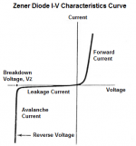
Let's think a little more about Jhstewart9's consideration. I attach the I / V curve of a Zener and the DB3 diac. Why is a Zener a good protection to avoid output spikes, while the DB3 Diac is not?
Attachments

the DIAC will still allow large enough transients that the inputs of some amplifiers will be damaged. It's a poor choice. A relay with a simple time delay transistor arrangement would be far better and can easily be implemented.
The diac DB3 is a pulse shaper part, very useful to trigger triacs. See the I/V diagram at post #35 from the DB3 datasheet. When the voltage increses beyond Vbo, it forces very rapidly the voltage between the terminals at the new value Vf. This will create a narrow pulse with delta V amplitude. The zener diode does not have this behaviour. If both positive and negative pulses need to be limited, two of them are needed. The zener value should be carefully selected to avoid any clipping at normal operating voltages. As Linwendil said, a time delay relay would be the optimal solution here.
That DB3 clipping is exactly what I want, as its output voltage is under 28V when it is under normal operation (2V RMS). When the output voltage appears to be 28V, the voltage level is almost to the power amplifier input damage level. So the clipping serves its most useful function as to decrease the voltage, while the zener keeps the voltage into a dangerous level which is I don't hope to. 🙂
Last edited:
the DIAC will still allow large enough transients that the inputs of some amplifiers will be damaged. It's a poor choice. A relay with a simple time delay transistor arrangement would be far better and can easily be implemented.
28V DB3 is good enough to protect the solid-state power amplifier input which is usually with resistors connected in series, serves as a buffer. I reckon that as protecting the circuit, there is a serious drawback for relay. However, don't forget what we're making right now is a preamplifier. There are many imperfections for relay. are many side-effects if using the relay:
1. The responese time for delay is 0.1S that is so slow, so even when the input peak volatge is about to damage (after starting), it is right before
the relay activation.
2. The signal path is longer.
3. You already added one more mechanical contact point in the circuit.
4. A DC magnet directly crosses the signal path wire.
5. Driver-relay circuit will add the interference and noise.
Therefore, you can see that the path is designed as the shortest distance when I design this circuit, I even cut the input selector. All components are designed to be within a compacted area. All about is to strive for excellence. For me, the relay is just like a toxic of the amplifier, that's why I chose the DB3 which is simple and enough.
The is a new method that was invented by myself. This is the reason why people usually don't understand this DB3 protection because they've never met this method before.
- Home
- Amplifiers
- Tubes / Valves
- DIY Marantz M7 using 6SN7 and 6SL7