AudioGANG,
Thanks for using a DC/AC current probe to do that measurement.
That scope trace is a wonderful training aid.
An analysis of the integral of Current-Squared (I-squared) will cause it to become apparent that the peak current is many times the average current that the capacitors can supply over time (over 360 degrees of the sine wave). The transient current is only for a few degrees of each alternation.
Therefore, the extremely large transient current, and the integral of I-squared times the winding DCR of the transformer secondary will heat it. Also, that transient load current on the primary winding DCR will heat it too.
If you change the filter to choke input (L then C), the current will be spread over a much larger number of degrees of each alternation. That means the I-squared current is lower, and the DCR of the secondary and DCR of the primary will have less heat loss (I-squared x R).
Of course, the cap input filter can output up to 1.414 times the secondary rms voltage (Well, we have to subtract the diodes voltage losses from that).
And, the choke input filter can only output up to 0.9 times the secondary rms voltage (Well, we have to subtract the diodes voltage losses, and the choke's DCR losses from that).
We may get back a little of that voltage, because there are less volts lost in the transformers secondary DCR and the primary DCR, because the peak current is much lower.
To get the choke input filter to work correctly we have to calculate and use an inductance equal to, or larger than the critical inductance.
If you get a chance, do the same experiment with a choke input filter, and the current probe and scope.
Be sure to reduce the 5k resistor to get the same load current. 5k x 0.9/1.414 = 3,182 Ohms gets close to the same load current, due to the reduced voltage to the load of the choke input filter.
Thanks!
I absolutely agree LC filter is better than RC filter,
Mr AudioGang has shewn us the current peak results. But what is required is the RMS results, here they are.🙂
I won't focus on RMS A, I think the most important is Peak A,Because Peak A has the biggest relationship with noise,
Mr AudioGang has shewn us the current peak results. But what is required is the RMS results, here they are.🙂
OK, but you would not use 4.7uFd with a 5k audio load, because high ripple.
Go 47u (kinda average) versus 470u (plenty oversize).
> I won't focus on RMS A
No, every time a large cap appears everybody screams "You'll burn your rectifier!" or even "transformer!". Actually, and of course, the Peak is rather closely controlled by the series resistance, which is expensive to make "small", so the peak current does not rise much after we get a "reasonable" size cap and ripple. But the transformer and rectifier will burn from heat, RMS. And the waveform is ugly, hard to get the RMS of.
And all-in-all..... We can cheaply buy rectifiers 3X and even 10X what an envelope calculation says we need. 1 Amp DC load, buy a 6 Amp, its only a buck. 10A power box? A 50A bridge is not expensive today. And I have *never* seen an audio amplifier burn its transformer except as part of a general dead-short melt-down. (Yes, several mystery failures traced to winding defects, not designable.)
RMS Definition
From Wikipedia
For alternating electric current, RMS is equal to the value of the constant direct current that would produce the same power dissipation in a resistive load.[1
Same as it was when I still had hair.
Notice the definition sez Power Dissipation in a Resistive Load.
Far as I know there are still no common transformers wound with super conducting materials.
For the mathematically inclined here is the link to RMS-
Root mean square - Wikipedia
All else is just somebodies opinion, blowing smoke.🙂
Pure sine waves have RMS voltage = Peak voltage/Root(2).
Peak voltage/~1.414 = RMS voltage.
RMS voltage x Root(2); (RMS volts x 1.414 sounds like the B+ voltage we get from a Capacitor Input filter.
When AC RMS voltage = DCV, the heating effect on a resistive load is the same.
For any wave-shape other than a pure sine wave, the relation of Peak voltage to RMS voltage is almost never the ratio of Root(2) (~1.414).
Yes, someone can come up with a funny wave-shape that also has a ratio of root(2), but not naturally unless it is a sine wave.
I hope I did not do a typographical error, or a calculation error.
Last edited:
Measuring RMS Voltages & Currents Before Digital Methods
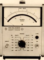
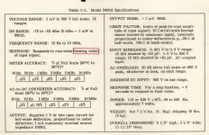
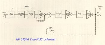
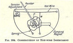
In earlier times voltage, current & power where often measured by a method of substitution, a meter face was calibrated with a known DC & than the unknown AC measured. The meter needs to be something that will respond equally to both AC & DC , a hot wire meter will do that. But those instruments are not very sensitive. They were rather common in apps not long ago on vehicles & so on. I have/had one that indicated 8-16 volts here but can't find it today. It may have gone in the pile of my stash I gave away last year. The HP 3400A True RMS Voltmeter (1960) amplifies the signal with a FB stabilized wideband amplifier. The front end is a bootstrapped 7586 Nuvistor. The instrument is accurate from 10 Hz to 10 MHz. That signal is applied to one arm of a thermocouple pair, the other arm applies the DC balancing signal. The DC signal is measured, that is what is indicated on the instrument meter.
By substitution an easy to measure low frequency variable DC makes measuring AC RMS easy. We sold many of these instruments, they were very popular.🙂
Attachments
From Wikipedia - For alternating electric current, .....
The qualification is not needed. For ANY waveform (even non-alternating or aperiodic) the RMS is same-as the heat value.
And the heat is one of the important limits on transformers.
WU KIN, Please don't be lazy,Just search for this number "SHM100KC15A" on the Internet
I found this, is it? thanks!
http://www.apexhk.com/designbymrk/assets/datasheet/SHM100KC15A.pdf
- Home
- Amplifiers
- Tubes / Valves
- DIY Marantz M7 using 6SN7 and 6SL7