Power efficiency can be maybe put aside on a small preamplifier like this one. The transformers on post #1 are beefy and should handle with ease the abnormal capacitive load that has been applied. The total part cost is probably about the same of a properly sized full wave rectifier. But I still dont'see any compelling advantage of half-wave rectification on this application. Reason #3 at post #59 is true, but it only matters when speakers are small and the amplifier has not been able to remove hum in the first place. I can not make sense of the other reasons listed in the post. Conversely, the half wave rectification greatly increases the pulsed electromagnetic field that is leaking from the power transformer, maximizing the chances of a stray coupling to high impedence grid circuits.
It may seem strange but the current pulses on the PT are symmetrical. The first +ve going charges the first cap while the next -ve going charges the other cap in the circuit. They add up to make the total, every other +ve or _ve pulse depending on how we see the circuit. But the end result is hum at the power frequency.🙂
Bunk!!😀
Increasing the capacitance increases the peak current applied to the PT. It is the RMS currents that cook transformers, not the average current. Looks like you have never heard of transformer winding utility factor, a measure of currents both AC & DC in the transformer windings, depending on whether the load is full wave of half wave, capacitor input to filter or choke, resister load or charging a battery. Better go back to school for a while, You have failed the power conversion in power systems test. The losses during conversion from AC to DC appear as heat. And even more losses in the core, both hysteresis & eddy currents, especially those caused by the harmonics caused by the AC to DC conversion.
In M7 Power.pdf I am using R2 (8ohm) to reduce peak current. We also use half wave doubler retification(is not half wave rectifier) so the it won't reduce much efficiency. You and I are using different way, you only consider efficiency and heat, I only care about the noise.I believe when we are making preamp, the power supply efficiency and heat and power factor etc... is not important.
Power efficiency can be maybe put aside on a small preamplifier like this one. The transformers on post #1 are beefy and should handle with ease the abnormal capacitive load that has been applied. The total part cost is probably about the same of a properly sized full wave rectifier. But I still dont'see any compelling advantage of half-wave rectification on this application. Reason #3 at post #59 is true, but it only matters when speakers are small and the amplifier has not been able to remove hum in the first place. I can not make sense of the other reasons listed in the post. Conversely, the half wave rectification greatly increases the pulsed electromagnetic field that is leaking from the power transformer, maximizing the chances of a stray coupling to high impedence grid circuits.
We also use half wave doubler retification(is not half wave rectifier) so there will not have a lot of pulsed electromagnetic field leakage. The leakage should be similiar to full wave or bridge rectifier.
It may seem strange but the current pulses on the PT are symmetrical. The first +ve going charges the first cap while the next -ve going charges the other cap in the circuit. They add up to make the total, every other +ve or _ve pulse depending on how we see the circuit. But the end result is hum at the power frequency.🙂
You finally understand. The main noise frequency is same as power line(50/60Hz), if you use bridge or full wave retificer, the main noise frequency will be double of the power line(100/120Hz). This is our circuit advantage. I only point out using lower frequency is easier to control. Of course the hum sound can be reduce but not disappear.
Now it's time to answer the third question, the reason we use shunt type VR is because the VR loading resistor relocate closer to preamp circuit. It can make the shorter signal path, and VR have only 3 wires (normal is 5 wires). As a result the noise is lower.
Bunk!!😀 Increasing the capacitance increases the peak current applied to the PT. It is the RMS currents that cook transformers, not the average current. ....
Everybody says that. But do math. The rms actually goes *down* when we super-size the cap... the worst-case is an undersize cap such as in plating or welding.
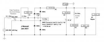
source 333V(0.2r)
Load 5k
4ufd 400VDC 140pp (35%) 7Apk 1Arms
40ufd 460VDC 20pp (5%) 6.5Apk 0.8Arms
400ufd 470VDC 2.4pp (0.5%) 3.5Apk 0.5Arms
Attachments
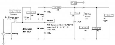
PRR, Can you increase R2 (8ohm)Between the transformer and the diode,Do simulation test once again ?😀
RMS vs Average Current in Rectifer Systems
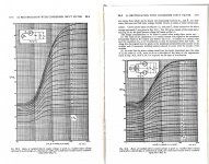
Its been a while since I calculated a Cap input rectifier system by the brute force method, that being calculus & the slide rule. Luckily for us, somebody I think in the late 30s did the hard work.
The attached pages from RDH4 tell us all we need to know. These same curves were reproduced in many texts covering electronic engineering.
I found that if the first cap after the rectifier was in the range where 2*PI*f*C*Rl was 10 to 20 there was a good trade off between ripple & the resultant RMS current. So the solution became something that could be solved on a four function calculator. Or pencil & paper.🙂
What simulator was used in post 67?
Attachments


Who is need back to school?
All of us can benefit by learning more about where we are, including electronics.
Referring to Figure 30.8 on page 1175 of RDH4 we can see that the RMS current could easily get to 5X the DC current. Total of the resistance/impedance of the source makes a large difference in the result. Adding some extra R in series with the rectifiers reduces the RMS/DC ratio.🙂
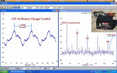
A good example were the source impedance is increased in the design is a common automotive battery charger. Build in some leakage reactance, problem solved.
All of us can benefit by learning more about where we are, including electronics.
Referring to Figure 30.8 on page 1175 of RDH4 we can see that the RMS current could easily get to 5X the DC current. Total of the resistance/impedance of the source makes a large difference in the result. Adding some extra R in series with the rectifiers reduces the RMS/DC ratio.🙂
A good example were the source impedance is increased in the design is a common automotive battery charger. Build in some leakage reactance, problem solved.
Attachments
I used PRR circuit diagram for a real test, The test results are as follows, I just record the most interesting peak A,
source 220V ac
Load 5K
4,7uF 1.2A peak
47uF 0.84A peak
470uF 0.65A peak
470uF + 8 ohm 0.42peak
source 220V ac
Load 5K
4,7uF 1.2A peak
47uF 0.84A peak
470uF 0.65A peak
470uF + 8 ohm 0.42peak

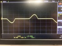
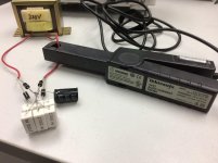
AudioGANG,
Thanks for using a DC/AC current probe to do that measurement.
That scope trace is a wonderful training aid.
An analysis of the integral of Current-Squared (I-squared) will cause it to become apparent that the peak current is many times the average current that the capacitors can supply over time (over 360 degrees of the sine wave). The transient current is only for a few degrees of each alternation.
Therefore, the extremely large transient current, and the integral of I-squared times the winding DCR of the transformer secondary will heat it. Also, that transient load current on the primary winding DCR will heat it too.
If you change the filter to choke input (L then C), the current will be spread over a much larger number of degrees of each alternation. That means the I-squared current is lower, and the DCR of the secondary and DCR of the primary will have less heat loss (I-squared x R).
Of course, the cap input filter can output up to 1.414 times the secondary rms voltage (Well, we have to subtract the diodes voltage losses from that).
And, the choke input filter can only output up to 0.9 times the secondary rms voltage (Well, we have to subtract the diodes voltage losses, and the choke's DCR losses from that).
We may get back a little of that voltage, because there are less volts lost in the transformers secondary DCR and the primary DCR, because the peak current is much lower.
To get the choke input filter to work correctly we have to calculate and use an inductance equal to, or larger than the critical inductance.
If you get a chance, do the same experiment with a choke input filter, and the current probe and scope.
Be sure to reduce the 5k resistor to get the same load current. 5k x 0.9/1.414 = 3,182 Ohms gets close to the same load current, due to the reduced voltage to the load of the choke input filter.
Thanks!
Last edited:
Post back the result pictures.
Your results are not complete, the winding resistance of the primary & secondary of the transformer needs to be included. Check the list on Image #1 on Post 69.
Then calculate the RMS value of the current. That is the part that causes much heating in transformers.🙂
- Home
- Amplifiers
- Tubes / Valves
- DIY Marantz M7 using 6SN7 and 6SL7