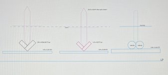
Had a quick look at the TC Vee plate alternative. By using the fibre optic cleaver 20mm diameter rolling on 1.5mm TC flat bar @90deg on 1.0mm GFS. I can get the axle height 0.419mm lower than 16mm diameter rolling on 4.0mm diameter rods. Even when rolling on 2.0mm TC plates (which might be easier to handle for polishing) only pushes the axle height up by 0.298mm beyond that of the 16mm diameter. See pic. I’m going to give both rail versions a go as I’ve nearly completed the niffy based version with the extra rail clamping alterations and I’m curious to see if they perform differently.
S
S
Attachments
You also need to include the mass of the wheel in the COG calculation because the whole wheel is above the pivot. Reducing the OD of the wheels only lowers COG slightly reducing the mass of the wheel will have a greater effect on COG.
I’ve ordered some cleaving wheels from AliExpress. When delivered I’ll try and photograph the cutting edge. @super10018 how do you plan to radius the edge accurately? Could there be a way of having the knife edge run in a TC radius groove? I know this is heading back to the Clear Audio solution but if implemented with the niffy inspired carriage it could be quite interesting.
S.
S.
Morning All! - i am intrigued by these ideas, it seems to me that if the wheel had a sharp edge as manufactured it would have a single contact point in the V bottom and that would lead to less rolling resistance, and also the warp following motion would be pivoting on that single point as opposed to scrubbing two, would that not be better? I don't understand this because, as some of you will know i use a different style of carriage, however other ideas are always fascinating!
M
I like the idea of retaining the factory knife edge as I would hope the tolerances would be higher. I think the only thing to do is just give all the options a go…keeps me out of trouble!
S.
S.
It will be interesting to see the reasons for those suggestions, these folk have good experience! - also there are lots of different ways to get good results, so if you can experiment and make comparisons that's good as well. One thing i learnt early on was to measure results. I was persuaded by contributors on this thread, I had pretty much always found that the work i had just done seemed to be an improvement.........I then learnt that auto suggestion is quite powerful, you've just done lots of work and intend and hope it results in an improvement, measurements often showed me otherwise!
I started out with ball bearings on glass rails, and now have a totally different solution, and scrap glass and ball bearings, which i believe gives better sound. However there are different compromises that also work..........
I started out with ball bearings on glass rails, and now have a totally different solution, and scrap glass and ball bearings, which i believe gives better sound. However there are different compromises that also work..........
Yes, there are many ways to achieve very similar results. One parameter is cost, it’s just rewarding to build hifi from something relatively inexpensive. However, I might regret ordering the least expensive fibre optic cleavers!!
S.
S.
From my recollection way back in this thread. There was a suggestion that the two contact points of the niffy double rail/ring wheel system benefited from the damping offered by the two contact points. However, rolling resistance/friction is increased. The knife edge vs the wheel/rods is a comparison I’m interested to try. Rolling resistance should be much lower with the cleaver wheels but as @warrjon says the wheels might be too heavy, moving COG up.
S.
S.
Cutting a radius groove into the top of TC rod for the cleaving wheel to run in could be possible. The drawing shows three radiuses with the focus on how to polish the bottom of the groove. The narrower, the more difficult. The wider, the more the wheel might track like a skateboarder in a half pipe but would be easier to polish? The rod could be held in a 4mm round pocket milled into aluminium block with 45deg jaws to guide the wheel back if unintentionally knocked?
S.
S.
Attachments
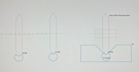
Cutting a radius groove into the top of TC rod for the cleaving wheel to run in could be possible. The drawing shows three radiuses with the focus on how to polish the bottom of the groove.
The issue with this approach is it's possible for the wheel to ride up the radius creating forward and aft movement. This is a similar issue the Clearaudio LTA has with the ball race bearing in a glass tube. Having a wheel run between 2 rods prevent this axial movement.
If I was designing this I would do as @super10018 suggested by adding a radius to the cleaver wheel and running it in the bottom of a Vee channel. IIRC Jim had to add viscous damping to his air bearing arm because of the very low friction you may need to do similar with this type of bearing.
Build it and see how it performs. I would suggest setting yourself up to measure the results. All you need is a laptop some free software, REW or Virtual Analyzer and a good quality USB sound card like a Behringer umc204hd.

Well, I suggest the rounded edge because the bottom of your V rail which is constructed with two pieces of plates may not be perfect. There may be some tiny space in between. That will cause more fiction for the wheels. If you have a precision-made V rail, it should be no problem with sharp-edge wheels.Morning All! - i am intrigued by these ideas, it seems to me that if the wheel had a sharp edge as manufactured it would have a single contact point in the V bottom and that would lead to less rolling resistance, and also the warp following motion would be pivoting on that single point as opposed to scrubbing two, would that not be better? I don't understand this because, as some of you will know i use a different style of carriage, however other ideas are always fascinating!
M
Here is a possible way to modify the wheels. Please see the rough drawing.
Hold the hard oil stone and make motions as the arrows indicate. Run the drill in revise so the screw won't loose. The edge may not be perfectly rounded, but it is ok as long as the edge doesn't touch the bottom of V rail.
I don't think it is a good idea at all.Cutting a radius groove into the top of TC rod for the cleaving wheel to run in could be possible. The drawing shows three radiuses with the focus on how to polish the bottom of the groove. The narrower, the more difficult. The wider, the more the wheel might track like a skateboarder in a half pipe but would be easier to polish? The rod could be held in a 4mm round pocket milled into aluminium block with 45deg jaws to guide the wheel back if unintentionally knocked?
S.
This is the reason why I settled on the niffy approach for my first LTA. Regarding the cleaver wheel, concentricity will be very hard to maintain if the precision factory edge is removed. The radius groove would maintain the factory edge, eliminate the mating surface issue of the TC vee plates. The Clear Audio design runs inside a much larger diameter glass tube. I was proposing a 1.0mm - 2.0mm groove. Depending on the surface finish of the radius groove there might even be tiny linear striations on the groove surface acting like tracks or guides. This might prevent lateral movement up the radius. I would prefer to maintain the factory edge of the cleaver, I’ll probably end up trying both. However, with the vee plate approach time would be better invested in the mating surfaces being spot-on.
S.
S.

Hi all,
It's been a while since I've caught up with this thread. Diyaudio doesn't seem to like sending me new post notifications.
Hi Sether.
Welcome to the thread.
I built my rail with the tungsten carbide rods seven or so years ago. I have had no issues with the rods becoming unglued. My bearing system using these rods, tungsten carbide rings and jeweled vee bearings has worked flawlessly for this entire time.
Initially I used borosilicate glass rods. I cannot take credit for the idea of using two rods for the rail. I believe that was a chap called Bill from Canada. I used the glass rods to develop the best rail and wheel configuration before I implemented the tungsten carbide rods. My first rail was made of acrylic. Later rail designs sounded much better. My current rail has a 1mm tool steel plate for the base with a channel made from carbon fibre batons. These have thick walled stainless steel tubes filled with damping material attached to them.

The rail was constructed layer by layer. Each layer was clamped as the epoxy cured. The clamped assembly was placed into an oven and the temperature increased to ~100°C left for an hour then the oven was switched off and allowed to fully cool before the assembly was removed, the clamps removed and the next parts added. Heat curing epoxy makes it much harder and stronger. This may be why I have not suffered my rods debonding even though they were very finely polished.
I got lucky with finding exactly the right size sapphire vees on Amazon (0.25mm radius) and at a good price. I haven't seen them since. I purchased my pivots (0.125mm radius) from Truepoint. My tungsten carbide rings were sold as wedding rings and are the smallest I've ever found at 15.7mm OD, if I remember correctly. They were from Vietnam. (slightly disturbed by the idea of a "wedding" rings this small). Luckily my rings were incredibly round, to within 10μm. Got lucky again.
It's been a while since I've caught up with this thread. Diyaudio doesn't seem to like sending me new post notifications.
Hi Sether.
Welcome to the thread.
I built my rail with the tungsten carbide rods seven or so years ago. I have had no issues with the rods becoming unglued. My bearing system using these rods, tungsten carbide rings and jeweled vee bearings has worked flawlessly for this entire time.
Initially I used borosilicate glass rods. I cannot take credit for the idea of using two rods for the rail. I believe that was a chap called Bill from Canada. I used the glass rods to develop the best rail and wheel configuration before I implemented the tungsten carbide rods. My first rail was made of acrylic. Later rail designs sounded much better. My current rail has a 1mm tool steel plate for the base with a channel made from carbon fibre batons. These have thick walled stainless steel tubes filled with damping material attached to them.
The rail was constructed layer by layer. Each layer was clamped as the epoxy cured. The clamped assembly was placed into an oven and the temperature increased to ~100°C left for an hour then the oven was switched off and allowed to fully cool before the assembly was removed, the clamps removed and the next parts added. Heat curing epoxy makes it much harder and stronger. This may be why I have not suffered my rods debonding even though they were very finely polished.
I got lucky with finding exactly the right size sapphire vees on Amazon (0.25mm radius) and at a good price. I haven't seen them since. I purchased my pivots (0.125mm radius) from Truepoint. My tungsten carbide rings were sold as wedding rings and are the smallest I've ever found at 15.7mm OD, if I remember correctly. They were from Vietnam. (slightly disturbed by the idea of a "wedding" rings this small). Luckily my rings were incredibly round, to within 10μm. Got lucky again.
I think that the two rod system has definite advantages over making a right angle out of two flat pieces as described by Super10018. Sorry Jim. If using a very sharp edged cutter for the wheel there would be a strong tendency for the wheel to bind. This tendency would be made worse if the join was not absolutely perfect. As suggested by Jim the edge of the wheel would need to be rounded to prevent this binding. The sides of the channel shown by Jim are at 90° to each other. Increasing this angle to say120° will reduce rolling resistance.
Using two round rods that are held tightly against each other and a flat base will create a very straight even channel. It would be very difficult to achieve this level of accuracy using flat sections. It's easier to use round rods.
If 4mm diameter rods are used and the wheel is 2mm wide the contact angle between the two rods will be my preferred ~120°.
As vertical articulation of the arm is going to be a fraction of a degree the contact angle of the wheel with the rods is not going to vary by very much at all. From the wheels point of view the rail would appear to be two flat pieces at 120°.
I found that having the edge profile of the wheels as being nearly square with only a slight radius was better than if the edge of the wheel was completely rounded. I did quite a lot of experimentation, making 7 different rails and a dozen sets of wheels. (I even designed one rail to fail just to make sure that it actually failed in the way I predicted. Luckily it did.)
Having 2mm wide wheels running on 4mm rods does add a little bit of friction to the vertical articulation of the arm. This level of friction is just about perfect for damping the vertical motion of the arm. 1.5mm wheels on 3mm rods might (or might not) be slightly better. I definitely wouldn't want to go lower than this.
Niffy
Oh yeah. Forgot to say. The diamond tipped engravers could be perfect as long as the tip radius isn't too small.
Thank you niffy for the insight into your design. I’m getting impatient to finally hear all the hard work! I was worried about using the diamond tipped engravers as pivots as normally pivots should be less hard than the seat, certainly would make a very fine pivot as long as it doesn’t erode the surface finish of the vee bearings. Regarding the 1mm tool steel plate at the bottom of your carriage design, I presume this is GFS if so would it be worthwhile quench hardening to increase stiffness further.
S.
S.
In the @niffy designed carriage yes it will place the COG way too high. I struggled to lower COG with 18mm wheels to be under the pivot.
With my arm set up with my current cartridge, Ortofon Quintet Black S, the pivot point is 1.6mm above the COG. This will result in less than a 1% variation in tracking force with even the severest warp.
Larger diameter wheels will inevitably raise the COG but they will also have lower rolling resistance. Wheels in the 15-18mm range are going to offer the best compromise between the two factors.
Niffy
- Home
- Source & Line
- Analogue Source
- DIY linear tonearm