The deflections in the previous post are only due to arm mass and don't take into account bearing friction, skating force or the flexibility of the arm wires.
Niffy
Niffy
As the stylus traces the groove it moves from side to side following the waveform of the music. At the peeks of this waveform the cantilever is aligned along the groove. On the centre line of the waveform the groove will be at an angle to cantilever. When the cantilever is aligned along the groove the drag on the stylus will be slightly less than when the groove is at an angle to cantilever. This variation in stylus drag causes a variation in tension alone the length of the cantilever. This variation in tension is a sound wave, also known as a compression wave.
The cantilever is mounted so that the stylus is free to only move vertically and horizontally. It is designed not to allow any movement alone the axis of the cantilever. The cantilever is rigidly coupled to the cartridge body along this axis. The sound wave is transmitted from the cantilever into the cartridge and from there into the arm.
This is the main mechanism by which vibrational energy is transmitted into the arm.
Compression waves will induce bending waves within the armtube. Bending waves also induce compression waves.
As the armtube flexes it wiggles the cartridge body around creating a false signal at the output of the cartridge. I believe that this is the single biggest problem with most record playing systems. Controlling the bending modes of the armtube is the most important aspect of tonearm design. Making the arm short makes controlling the bending modes much easier. Making the arm short dictates that the arm has to be linear tracking.
The compression waves from the cartridge don't just induce bending waves. They also propagate down the arm at the speed of sound for the material the arm is made from. When the wave hits a boundary between two materials with different mechanical impedance it reflects back. This could be between the rear of the arm and the air. By far the biggest reflections tend to be from the counterweight. Counterweights are often decoupled to prevent this reflection. Decoupling the counterweight usually puts a compliant layer between the counterweight and armtube/stub. This allows the weight to move around relative to the armtube. Decoupling the counterweight usually causes a lot more problems than it solves.
Making the counterweight smaller and lighter will reduce the strength of reflection. Luckily a shorter tonearm requires a lighter counterweight.
By the time that a sound wave has propagated down the arm, reflected off the counterweight and travelled back down the arm to the cartridge it is likely to be at a different phase. With some frequencies the reflection will be in phase and with others it will be out of phase. Ideally we want the phase difference between the source and the reflection to be as small as possible.
The speed of sound through aluminum is around 6000m/s. The distance from the headshell to the counterweight is typically around 250mm with a pivoted arm. At 1khz the reflection will be 30° out of phase. At 6khz it will be 180° out of phase.
The ideal material would have the highest possible speed of sound, beryllium would be great with a speed of sound of 12800m/s. Unidirectional carbon fibre has a speed of sound of 10000m/s. Woven/unidirectional carbon fibre laminate has a speed of sound of around 7500m/s. With my arm the counterweight is about 75mm from the headshell. At 1khz the reflection will be 7.2° out of phase. At 25khz it will be 180° out of phase.
With my arm the entire arm is in a similar state of compression or extension with little phase difference between the source and reflection across most of the audio band.
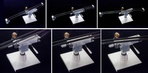
Of the six degrees of freedom the carriage only needs to be free to move in two of them. Coupling the carriage to the rail as solidly as possible in the other four will allow as much energy as possible to propagate out of the carriage into the rail and away from the cartridge. Mounting the carriage on spikes, the pin bearings, is a very effective way of coupling the carriage to the rail. Compression waves can induce some types of bearing (mainly ballrace) to sympathetically vibrate, chatter. As pin bearings are under constant load they are not prone to chatter.
It may seem beneficial to decouple and isolate the carriage from the rest of the deck to prevent motor noise, environmental noise and bearing rumble from entering it. By far the greatest level of vibrational energy entering the tonearm is from the stylus groove interface. It is much better to create a path to allow some of this energy to escape rather than trying to stop the very low levels from other sources from entering.
Hopefully this sheds some light on some of my design decisions.
Niffy
The cantilever is mounted so that the stylus is free to only move vertically and horizontally. It is designed not to allow any movement alone the axis of the cantilever. The cantilever is rigidly coupled to the cartridge body along this axis. The sound wave is transmitted from the cantilever into the cartridge and from there into the arm.
This is the main mechanism by which vibrational energy is transmitted into the arm.
Compression waves will induce bending waves within the armtube. Bending waves also induce compression waves.
As the armtube flexes it wiggles the cartridge body around creating a false signal at the output of the cartridge. I believe that this is the single biggest problem with most record playing systems. Controlling the bending modes of the armtube is the most important aspect of tonearm design. Making the arm short makes controlling the bending modes much easier. Making the arm short dictates that the arm has to be linear tracking.
The compression waves from the cartridge don't just induce bending waves. They also propagate down the arm at the speed of sound for the material the arm is made from. When the wave hits a boundary between two materials with different mechanical impedance it reflects back. This could be between the rear of the arm and the air. By far the biggest reflections tend to be from the counterweight. Counterweights are often decoupled to prevent this reflection. Decoupling the counterweight usually puts a compliant layer between the counterweight and armtube/stub. This allows the weight to move around relative to the armtube. Decoupling the counterweight usually causes a lot more problems than it solves.
Making the counterweight smaller and lighter will reduce the strength of reflection. Luckily a shorter tonearm requires a lighter counterweight.
By the time that a sound wave has propagated down the arm, reflected off the counterweight and travelled back down the arm to the cartridge it is likely to be at a different phase. With some frequencies the reflection will be in phase and with others it will be out of phase. Ideally we want the phase difference between the source and the reflection to be as small as possible.
The speed of sound through aluminum is around 6000m/s. The distance from the headshell to the counterweight is typically around 250mm with a pivoted arm. At 1khz the reflection will be 30° out of phase. At 6khz it will be 180° out of phase.
The ideal material would have the highest possible speed of sound, beryllium would be great with a speed of sound of 12800m/s. Unidirectional carbon fibre has a speed of sound of 10000m/s. Woven/unidirectional carbon fibre laminate has a speed of sound of around 7500m/s. With my arm the counterweight is about 75mm from the headshell. At 1khz the reflection will be 7.2° out of phase. At 25khz it will be 180° out of phase.
With my arm the entire arm is in a similar state of compression or extension with little phase difference between the source and reflection across most of the audio band.
Of the six degrees of freedom the carriage only needs to be free to move in two of them. Coupling the carriage to the rail as solidly as possible in the other four will allow as much energy as possible to propagate out of the carriage into the rail and away from the cartridge. Mounting the carriage on spikes, the pin bearings, is a very effective way of coupling the carriage to the rail. Compression waves can induce some types of bearing (mainly ballrace) to sympathetically vibrate, chatter. As pin bearings are under constant load they are not prone to chatter.
It may seem beneficial to decouple and isolate the carriage from the rest of the deck to prevent motor noise, environmental noise and bearing rumble from entering it. By far the greatest level of vibrational energy entering the tonearm is from the stylus groove interface. It is much better to create a path to allow some of this energy to escape rather than trying to stop the very low levels from other sources from entering.
Hopefully this sheds some light on some of my design decisions.
Niffy

I have read this several times now, many thanks Niffy.
It adds to my knowledge and will be used in future iterations! - i hope it helps others as well.
One immediate question if i may please;
At the termination of the arm, or any part thereof, where reflection might occur, is there a validity to shaping the end to achieve reflection at angles, rather than a square end reflecting it straight back, for example a rod, cut square across or rounded?
Thanks again
Mike
Hi Mike,
The reflection of sound waves within the structure of the tonearm will, to some extent, be modified by its shape.
By changing the end of a rod from flat to round will have little effect. If the rod is 12mm in diameter, a 6mm radius, the difference in the timing of reflections would be measured in microseconds. For aluminium, with a speed of sound of 6000m/s, a 6mm quarter wave, which would result in a 180° phase difference would be at 250khz. Way outside of the audio band.
This is similar to the advantages of using nonparallel walls in a loudspeaker. There is little benefit until the wavelength of sound is smaller than the dimensions of the speaker cabinet. There is no advantage to making subwoofer cabinets nonparallel as the wavelength is much greater than cabinet dimensions. In the midrange and up nonparallel cabinet sides make a big difference. Likewise making the inner surface of the cabinet uneven will have little to no effect if the size of the unevenness is less than a couple of inches which is the wavelength of sound at ~7khz. Most tweeters are closed back so don't radiate into the cabinet. If using full range drivers making the cabinet walls with undulations down to 1inch can be beneficial as this type of driver does radiate high frequencies into the cabinet.
There may be some advantage to having multiple points of weak reflection, making the reflection more chaotic and smearing the arrival time from a single peek.
Generally I would say reducing the strength of any reflection and the time taken for the reflection to echo back are more important than breaking up the reflection.
Niffy
Last edited:
I haven't read back to check, but do not recall having read about potential to reduce the strength of reflections.
Apologies if i missed that, what might be possible there please.
Many thanks Niffy for your informative feedback!
M
Apologies if i missed that, what might be possible there please.
Many thanks Niffy for your informative feedback!
M
The main way to reduce the strength of the reflection is to make the counterweight as small as possible.
You get a much smaller echo from a single brick than from an entire wall.
Luckily a short tonearm requires a much smaller counterweight.
Another way to reduce the strength of reflections is to reduce the difference in the mechanical impedance between the various parts of the arm. The best way to achieve this is to make the arm from as few a number of pieces as possible and to make the different pieces from the same material. A single piece is ideal. It is usually impractical to make the counterweight from the same material as the armtube.
In my design the majority of the counterweight is the rear part of the single piece carbon fibre carriage. A small additional weight is used for tracking force adjustment. This allows the counterweight to be made smaller still.
This has the additional benefit that most of the counterweight is also part of the structure of the carriage and is used to further increase carriage rigidity.
Niffy
@niffy I'm in the process of building 3 new LTA's using pin bearing wheels. A friend of mine who is doing the CNC machining is making new wheels and axles from a single piece of tool steel which will be nitride hardened. When I have the prtotype I'll post a pic of the new wheels.
Hi Warren,
Sounds cool. Have you considered titanium? As hard and rigid as tool steel but only half the density. I did try to make my entire wheels from titanium but it proved beyond my capability. My wheels are titanium with tungsten carbide rims, just the hubs and axles are aluminum.
Niffy
Sounds cool. Have you considered titanium? As hard and rigid as tool steel but only half the density. I did try to make my entire wheels from titanium but it proved beyond my capability. My wheels are titanium with tungsten carbide rims, just the hubs and axles are aluminum.
Niffy
We looked at a number of rings and the smallest size I can gett is about 18mm OD this makes the COG of the carriage difficult to place under the vertical pivot. The other issue is none of the rings are perfectly concentric and thickness varies. Machining our own wheels they will be well within 0.005mm tolerance. I can't remember which tool steel Kev was using but he said it would be very close to the RC of carbide with Nitriding.
I have sent him message to ask about Titanium. The goal is better concentricity and reduced inertia and 16mm OD.
I have sent him message to ask about Titanium. The goal is better concentricity and reduced inertia and 16mm OD.
Hi Warren,
Reducing the mass of the wheels will definitely help to lower the COG of the carriage as the entire wheel is above the pivot point.
I must have been exceedingly lucky with the purchase of my tungsten carbide "wedding" rings. They were very circular and very small. I haven't been able to find rings this small again. They were also really cheap at about £3 each.
Is the Nitriding just a surface treatment similar to anodising? If so the thickness of the treatment will have a big impact on rolling resistance.
Another possible material to make the wheels from is sapphire. Round sapphire "windows" are available in many different sizes and thicknesses. How circular these are would be the limiting factor. The edges would need to be polished. Another problem would be how to attach them to the hub/axle as they do not have a hole in the centre. Sapphire should be even better than tungsten carbide.
Niffy
Kev is going to look into titanium and see what he can source . Gas Nitride hardening is not a coating like TIN it's hardening the surface to a specified depth. Nitride hardening is used on high performance engine crankshafts.
I have a few sets of carbide rings and every one is eccentric some worse than others. I used the best 2 I had. When testing rolling resistance of my carriage it was obvious there was a spot on the wheels where the carriage stopped. I marked the wheels and they stopped at the same point on the wheel every time, although they were still a vast improvement on the ball race bearings.
Sapphire is a good suggestion. I'll investigate it.
# 4611 to # 4947 et seq. The no-rail linear TA problem
Done, and working smoothly.
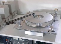
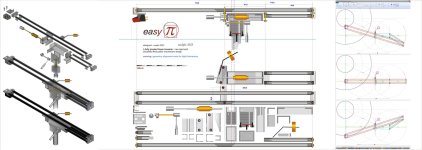
Attachments: simulation - design draws - photos of the tonearm - "crash test" videos
ciao - carlo
special thanks to Mike and Doug for their precious advices... and patience.
Done, and working smoothly.
Attachments: simulation - design draws - photos of the tonearm - "crash test" videos
ciao - carlo
special thanks to Mike and Doug for their precious advices... and patience.
Attachments
Impressive design, but IMO the main advantage of linear tonearms is when they are short (3 - 4 inches) to control stiffness / resonance.
This arms seems to be some 14 inches long; I wonder how much is "gained" overhang-wise when compared to a normal pivoted 14 inch tonearm.
This arms seems to be some 14 inches long; I wonder how much is "gained" overhang-wise when compared to a normal pivoted 14 inch tonearm.
Morning all,
Good response daanve. This is a staggering achievement, everyone has been asking for years for true linear movement, and here it is without a lateral carriage - Wow!!
Of course it will also have it's compromises, stiffness, resonance etc, and as everyone can see in the thread above i am in the short (est!?) arm brigade but they all have challenges to resolve and this is immediately better in some respects than every PTA almost anyone has made because of its true linear movement with bearings only, and people probably acclaim many PTA's without linear movement to be the best that can be done, so it surely has potential!?
M
A mechanical watch is far more desirable than a quartz watch even though the quartz watch will be more accurate.
My arm design is in some ways like the quartz watch, designed for maximum accuracy. The pivoted tangential tracking arms are like a skeletal mechanical watch. Incredible mechanisms for achieving the same thing by much more complicated means. They won't sound as good but I don't think that is the point. They are about the aesthetics of a fabulously complicated piece of engineering.
Just because I've gone down the maximum accuracy route doesn't mean I can't appreciate, neigh love, pivoted tangential arms.
And for sure Niffy, elegant it is, just as we would expect from Carlo!
It will be interesting to hear his impression of the sound when he gets that far, after all he has constructed a good number of class acts to compare it with!
It will be interesting to hear his impression of the sound when he gets that far, after all he has constructed a good number of class acts to compare it with!
I have recently made an upgrade to my tonearm, the first since I finished building it almost exactly 7 years ago.
I had made a heavier counterweight a couple of years ago to accommodate a cartridge upgrade but I don't think this counts as an arm upgrade.
My recent upgrade was to change the arm wire from the magnet wire I had been using to some Audionote Kondo arm wire.
The old arm wire was made of four stands of 0.08mm enamelled copper twisted together. Two strands were used as the signal positive and two for the negative. Separate runs were used for each channel.
The Kondo is made of four strands of 0.12mm high purity age annealed silver, twisted together.
The normal way of using the Kondo would be to use a separate run as supplied for the positive and for the negative for each channel, four runs in total.
In order to keep the wire flexible I used the Kondo in the same way I had used my previous wire, splitting out two strands each for positive and negative.
I had rewired an arm for a friend using this wire and it had made a surprisingly big difference so I thought it would be worth trying on my arm.
The sound quality difference was very similar to what we had found with my friends arm. The sound is much smoother right through the frequency range. The old wire had a coarseness and grain that I hadn't noticed until it was gone. The top end is sweeter and extended. The bottom end is fuller with more weight. There is greater transparency and better layering to the soundstage.
The Kondo is expensive at £250 for 2 metres. This does include solid silver cartridge clips. To me the upgrade has been worth every penny.
Niffy
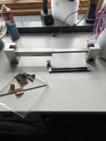
Hello everyone, I feel I’m very late to this party but I’ve been enthralled by this thread for months, some truly ingenious ideas! I’ve finally gathered together some materials and commenced on a variation/combination of Niffy and Warrjon’s design, see progress so far. The plan is to use this LTA on my Garrard 401 with some kind of custom plinth. I’m having trouble sourcing the vee bearings as from reading in previous posts many of you have experienced similar problems. I’m based in the UK and Truepoint’s website keeps redirecting me somewhere else? Have any of you found alternatives in the UK or have any of you over ordered and have spares which I could purchase? Also @warrjon a few threads ago, I see you machined a pocket carrier for the 4mm TC rods after experiencing adhesion problems with the epoxy. I was literally about to mix up the araldite when I read this! Is it due to the extremely smooth surface finish on the rods, @niffy are you seeing similar on your composite rail block or should I just throw caution to the wind!?
Sether
Sether
Attachments
Sether, great to see you following some of these intriguing constructions, no doubt influenced by the fine work these folk do in setting out information and opinions, like Niffy, NOCDPLZ and Warrjon in recent posts, and many others in the past.
We look forward to seeing your progress, i am interested to know what you are running at the moment?
As you say, it makes enthralling reading and i would like to take the opportunity to encourage such contributions and thank them for their efforts, as they constantly inform and challenge my thinking!
More please folks, any time you're feeling informative!
M
Hi Mike, thank you for the kind response. The knowledge which all the contributors have is simply incredible, it’s such a shame i came across this thread so late. In the true spirit of diy audio I can see many similarities to the Clear Audio design but with significant gains through group prototyping and subsequent improvements, truly astonishing…and on a budget! Reading back through the thread I can’t help thinking about the pin bearings and that something I use with my work would have perhaps been an option which is TC tipped engraving tips, the type used for cleaning fossils?! This is of course before the implementation of the far more accurate sapphire vees and TC pivots. I might have to try these if i fail to source from the UK. My interest in HiFi is quite broad, from restoring vintage speakers to complete speaker builds. I attach image of a horn which I’m working on utilising a planar magnetic mid/tweeter. However, my current setup which is sounding quite beautiful is a pair of 50 year old KLH model 28 omnidirectional speakers with a pair of omnidirectional super tweeters which I’ve built using AMT drivers.
S

S
Last edited by a moderator:
- Home
- Source & Line
- Analogue Source
- DIY linear tonearm