I guess that surface noise, hiss, click, pop is the single worst thing about vinyl?
If that is the case then reductions are a very interesting area.
Can anyopne explain the science of that to me please? Also if the structure damps that noise is it also damping other desirable high frequency noise? I frequently delude myself with improvements that turn out not to be so!............ and have indeed experienced a reduction of click/pop/hiss, thinking it to be good only to find snare drums disappeared as well, how does the damping chose bad from good. My iterative experimentation suggests Warren is benefitting from higher stiffness more than damping and i am intrigued to learn more!
Best
Mike
Click/pops on the LP are extremely fast transients, what you are actually hearing is the shock wave exciting the tonearm. Stiffening the rail structure has reduced the effect of these shock waves. Detail and frequency response of the music content will be influenced by the tonearm. If the TA has a resonance this will mechanically amplify the signal at that frequency and associated harmonics.
My SP10mk2 also has highly modified motor using an inverted bearing and custom POMC/Aluminium platter in Permalli plinth. These changes also made a major improvement in surface noise, which improved all the micro detail in the music.
If you place a stethoscope on a stock SP10mk2 platter mat and play some music (CD, tidal etc) you can clearly hear the music being amplified in the platter, the cartridge will hear this and mix it with the signal coming from the LP. Adding POM to the top of the platter and this acoustic feedback drops to inaudible levels. The Permalli plinth also made a large improvement the results of an impact test between the resin/bentonite and Permalli plinths showed a 20dB drop in transmitted noise above about 200Hz I can't remember what it was below 200Hz but I do remember it was still significant.
The change I made had a positive effect on SQ, there was a noticeable improvement in percussion, the textural rendering of cymbals is where it was most noticeable.
Damping - this is a contentious one and has issues where most just randomly add damping without information on what that damping is actually doing. My LTA has NO added damping. Damping is useless once the arm is resonating as this resonance is causing the arm to flex, damping will change the behavior including the Q. If damping is applied incorrectly it can make the resonance worse by spreading over a wider area and lowering it's frequency potentially increasing its amplitude. My DIY PTA had only a very small amount of damping applied, just enough to lower the peak of the main arm wand resonance.
EDIT: I should add in a TA with a hollow wand it's advisable to use some kind of fill inside the wand to prevent piping. In my TA I added a single bit up the wand just forward of center to prevent the air inside the wand resonating.
Last edited:

Always interesting to read your thoughts Warren, and i hope i understand them well.
Winter is only a few months away now...........what is the best (inexpensive and available) d.iu.y. alternative to Permali, i can feel a re-work of the plinth and supports will be worthwhile at some point..........
Winter is only a few months away now...........what is the best (inexpensive and available) d.iu.y. alternative to Permali, i can feel a re-work of the plinth and supports will be worthwhile at some point..........
I found one reference...............
https://www.scientificamerican.com/...-speeding-bullet-mdash-it-rsquo-s-super-wood/
https://www.scientificamerican.com/...-speeding-bullet-mdash-it-rsquo-s-super-wood/
You can try Permali at reasonable price, here
https://www.lencoheaven.net/forum/index.php?topic=42484.0
https://www.lencoheaven.net/forum/index.php?topic=42484.0
Thanks TD 150, i have read the 3 pages of posts and cannot see that anyone successfully purchased something yet, do you know any more please?
Best
M
Best
M
Once I had a Philips automatic turntable that featured a linear arm. It worked with some stepper motor and feedback to control the movement along the track. Sounded decent. Very inspiring project, it tickles my diy nerves to go along this route. Not easy but as you write very rewarding 🙂
Mike56,
You may PM analogadikt, he would respond. He is also on this forum with the same handle.
You may PM analogadikt, he would respond. He is also on this forum with the same handle.
http://www.grammofoon.com/Philips/Philips_70FP440.htm

Hopefully not too far off topic... this tone arm worked with a servo, controlled by a photoresistor and controller. Would this be of interest to imitate?
Hopefully not too far off topic... this tone arm worked with a servo, controlled by a photoresistor and controller. Would this be of interest to imitate?
I know this is off topic but thought I'd post these for anyone interested. These are the impulse tests between the R/B and Permalli plinths. The motor and platter were moved from the R/B to the Permalli plinth and the impact was at the same place WRT the platter and TA mount. Measurement was taken with the stylus sitting on a stationary LP at the output of the phono-pre.


Thank you TD150 and Mike 56Thanks TD 150, i have read the 3 pages of posts and cannot see that anyone successfully purchased something yet, do you know any more please?
Best
M
Permali boards are in stock and orders received are under process. Some people asked for small or odd sizes and if I cut up a 2x1 sheet for a small section , the entire sheet gets blocked so I have to wait and club orders.
If requirements and shipping destination is informed , I can quote in a day or two and ship in a about eight ten days once quote is approved. I am holding the stock of sheets in the factory premises only to facilitate cutting.
The Permali components for Lenco turntables are already received, I shall be making the announcement today.
@Mike56 , feel free to contact me with details of requirements.
Regards,
Thanks Analogadikt, its a busy time of year for me, but come the winter i will look at a new plinth etc, meanwhile would be very pleased to see delivered results, i do also have a Lenco.................might build it up one day!!
M
M
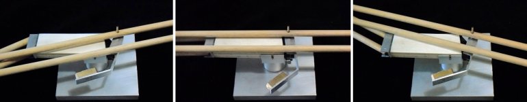
near the finish line?
This arm is really a challenge, now I've discovered that the solution designed for the CW is not enough for the task.
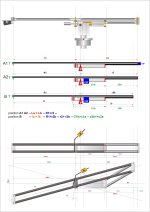
Since the projections of the distances La=Lb and la = lb are always equal, the way to have a constant CW balance seemed to make the pivot P aligned to the intermediate joint.
I wasted some time on it but it seemed not feasible, so the vertical pivot was brought as close as possible, hoping that in this way (A2) the variation should be minimal. So much that in the mockup a <15 grams CW very near to P is enough for balance.
But there was still a variation of about 1/4 VTF (!), and surprisingly not too different from A1 solution
No idea how to bypass this issue, but friend Mike(56) gave me the right hint:
"Any horizontally turning lever can be picked, and add an orthogonal lever in opposition to the shortening lever length will generate the compensation torque?"
And here we are:
the center lever (better the short one with its greater angle) is the only one that moves back 'n forth = the right way to balance the VTF variation. A tuning weight is attached via an angled rod - the 90° side determines the shift length - and the 45° one + the cw mass determines the recall.
The device works perfectly: simply taped to the mockup, the VTF variation is now under 0,1 g and can be tuned to zero.
With the further advantage that the center lever that helds off axis all the moving parts, now is somehow balanced by the side cw.
carlo
thanks again, Mike + Doug
This arm is really a challenge, now I've discovered that the solution designed for the CW is not enough for the task.
Since the projections of the distances La=Lb and la = lb are always equal, the way to have a constant CW balance seemed to make the pivot P aligned to the intermediate joint.
I wasted some time on it but it seemed not feasible, so the vertical pivot was brought as close as possible, hoping that in this way (A2) the variation should be minimal. So much that in the mockup a <15 grams CW very near to P is enough for balance.
But there was still a variation of about 1/4 VTF (!), and surprisingly not too different from A1 solution
No idea how to bypass this issue, but friend Mike(56) gave me the right hint:
"Any horizontally turning lever can be picked, and add an orthogonal lever in opposition to the shortening lever length will generate the compensation torque?"
And here we are:
the center lever (better the short one with its greater angle) is the only one that moves back 'n forth = the right way to balance the VTF variation. A tuning weight is attached via an angled rod - the 90° side determines the shift length - and the 45° one + the cw mass determines the recall.
The device works perfectly: simply taped to the mockup, the VTF variation is now under 0,1 g and can be tuned to zero.
With the further advantage that the center lever that helds off axis all the moving parts, now is somehow balanced by the side cw.
carlo
thanks again, Mike + Doug
Attachments
Intriguing progress Carlo, it will be interesting in a final version and depending on the bearing type whether they prefer (work better!) with some side load giving a pre-loading that avoids chattering or as equally balanced as possible, reducing frictions and not chattering because they are sufficient tolerance..........
Meanwhile, i am a bit surprised at the relative silence on this topic so far on the thread, this is an awesome possibility for a true radial motion without rails. My home grown "monkey" RTA is performing and measuring very well, but if Carlo brings this alternative to fruition i might even have a go to build one for myself!
M
I've been quiet because I'm not a fan of pivoting tangential TA's and felt I had nothing constructive to add. They are the worst of both worlds. Long arm wands that will resonate and bend and skating force. IMO negating any advantage of tracking error reduction.
Carlo the reason VTF is varying is because the arm circled in red is moving forward and backwards WTR the vertical pivot. Have you considered moving the vertical pivot to the cartridge end like the Dynavector this way you could increase the horizontal structure beams hence increasing rigidity.

Carlo the reason VTF is varying is because the arm circled in red is moving forward and backwards WTR the vertical pivot. Have you considered moving the vertical pivot to the cartridge end like the Dynavector this way you could increase the horizontal structure beams hence increasing rigidity.
I assume its the other way round in the measurements, Permali first, not in the order of the text? BTW, can you scale them to the same vertical axis, to demonstarte the difference.I know this is off topic but thought I'd post these for anyone interested. These are the impulse tests between the R/B and Permalli plinths. The motor and platter were moved from the R/B to the Permalli plinth and the impact was at the same place WRT the platter and TA mount. Measurement was taken with the stylus sitting on a stationary LP at the output of the phono-pre.
View attachment 1202402View attachment 1202403
Permalli is the second plot. Unfortunately Audacity automatically does the scale and try as I might I couldn't get it to scale them the same.
Very similar to the Technics SL-xx series of parallel tracking turntables. The mechanics/electronics can be adapted to a much more substantial tonearm assembly, if you desire. You could make a Pioneer PL-L1 homage.http://www.grammofoon.com/Philips/Philips_70FP440.htm
View attachment 1202349
Hopefully not too far off topic... this tone arm worked with a servo, controlled by a photoresistor and controller. Would this be of interest to imitate?
I'm not a fan of pivoting tangential TA's... #5075
The funny thing is that I agree - at least in part - Warren: and from experience (a pair of good working PTTA done in the past).
But since this pivoting linear has nothing to deal with pivoting tangential TA's, the only way to get a sensible opinion on a new (?) completely different geometry (line, not Thales circle) and force distribution is to understand it first*, and then to explore practically its effective geometric and mechanical feasibility.
Frankly, the fact that the mockup with wooden bearings passed without skipping my eccentricity test, difficult for many linear trackers, forces me to go on.
carlo
*eg, the reason for the VTF change is that all the levers shift forward to the 3 fixed pivots, but the rear control levers at twice the angle of the main ones; The position/relationship of pivots is strictly determined.by the Peacellier AP=BP condition; how could be used the split plane strategy?
Last edited:
Trying to overlay in my mind the big reduction is in 50-60Hz area wheras at low frequencies (single digit) and higher at ~2000Hz its higher, how does one decide which are more important, other than it sounds better!Permalli is the second plot. Unfortunately Audacity automatically does the scale and try as I might I couldn't get it to scale them the same.
M
- Home
- Source & Line
- Analogue Source
- DIY linear tonearm