It's great to see this thread still going and all the great builds . As is becoming clearer is that because this is a passive mechanical tracker dimensioning is key. I did a lot of work in the dimensioning and you can't take too much for granted here. I also came across the clearaudio arm dimensioning, this came into play with the final dimensioning for a large part. Stability is key, I found you should be able to take the wand with headshell and cw attached and rock it on a flat surface side to side with it settling quickly. The slung cw also goes above the record surface, no need to lower it below record surface with the hanging style of bearing assembly. I initially had the cw further away from the pivot but since found bass improved with the weight closer to the pivot along with lower noise floor and improved tracking.
Colin
Colin
jplesset, I used a tile saw. Worked great. I simply setup some wood blocks on either side of the blade so the tip of the blade was within the tube. It was then a simple task to send the tube down two passes to get the gap right. Plenty of water kept the cut clean.
I did three simple tests to evaluate the performance of my diy arm. The cartridge I used was Denon DL-S1. VTF was 1.3-1.5 g.
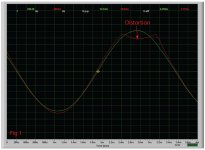
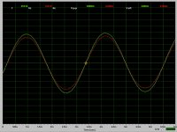
First test I did was to use Band 1, Band 4 and Band 8 on Hi-Fi News Analogue Test LP. These three bands are identical, but they are on different locations of the LP. It is basically a simple 300Hz waveform at high amplitude, 15 db. I only posted one screen image because the performances of the diy arm were basically same on different locations. Please see Fig 1. In this test, the arm tracked the left channel (green line) almost perfectly. However, there was a distortion at the peak of right channel (red line).
I also used two bands from Stereo Review's Stereo Test Record for Home and Laboratory Use, 1969 LP to do the 2nd and 3rd tests.
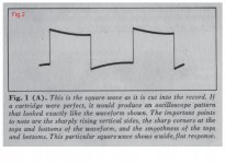
Second test utilities band 1 of Stereo Review's Record, square-wave tests. Please see fig 2. Fig 2 shows the square wave as it is cut into the record. If a cartridge were perfect, it would produce an oscilloscope pattern that looked exactly like the wave form shown. The important points to note are the sharply rising vertical sides, the sharp corners at the tops and bottoms of the waveform, and the smoothness of the tops and bottoms.
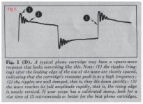
According to the instruction of this test LP, a typical phono cartridge may have a square-wave response that looks something like this. See Fig 3. Note: (1) The ripples (ringing) after the leading edge of the top of the wave are closely spaced, indicating that the cartridge's resonant peak is at a hight frequency; (2) The ripples are well damped, that is, the die down quickly; (3) The wave reaches its full amplitude rapidly, that is, the rising edge is nearly vertical.
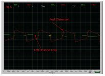
Now, let's see my diy arm test results. For left channel, Fig 4(green line), it looks not bad at all. The signal rises rapidly and falls rapidly. It also clearly indicates the peak point. Afterwards, it has very little ringing. But for right channel Fig 5, (red line), It doesn't show the peak point although it has very little ringing as well. But it also shows a fair amount of current from left channel. The results here are consistent with 1st test. The arm tracks left channel better than it tracks right channel.
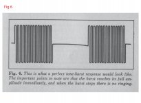
Third test is tone-burst test. Please see Fig 6. This is what a perfect tone-burst response would look like. The important points to note are that the burst reaches its full amplitude immediately, and when the burst stops there is no ringing.
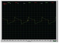
My tone arm did well in this test. See Fig 7. Although there were some ringing, the amplitudes for both channels rise and fall pretty fast. Again, right channel (red line) has more ringing than left channel(green line). This result is consistent with other two tests.
For now, I think I am not going to do anything because it doesn't affect the listening. The only thing I can think about is to loose the "knife edge effect' between the bearings and glass tubing.
Last, I would like to mention one thing to all the diyers who may be interested of building this tone arm.
Don't use glue on critical joints.
First test I did was to use Band 1, Band 4 and Band 8 on Hi-Fi News Analogue Test LP. These three bands are identical, but they are on different locations of the LP. It is basically a simple 300Hz waveform at high amplitude, 15 db. I only posted one screen image because the performances of the diy arm were basically same on different locations. Please see Fig 1. In this test, the arm tracked the left channel (green line) almost perfectly. However, there was a distortion at the peak of right channel (red line).
I also used two bands from Stereo Review's Stereo Test Record for Home and Laboratory Use, 1969 LP to do the 2nd and 3rd tests.
Second test utilities band 1 of Stereo Review's Record, square-wave tests. Please see fig 2. Fig 2 shows the square wave as it is cut into the record. If a cartridge were perfect, it would produce an oscilloscope pattern that looked exactly like the wave form shown. The important points to note are the sharply rising vertical sides, the sharp corners at the tops and bottoms of the waveform, and the smoothness of the tops and bottoms.
According to the instruction of this test LP, a typical phono cartridge may have a square-wave response that looks something like this. See Fig 3. Note: (1) The ripples (ringing) after the leading edge of the top of the wave are closely spaced, indicating that the cartridge's resonant peak is at a hight frequency; (2) The ripples are well damped, that is, the die down quickly; (3) The wave reaches its full amplitude rapidly, that is, the rising edge is nearly vertical.
Now, let's see my diy arm test results. For left channel, Fig 4(green line), it looks not bad at all. The signal rises rapidly and falls rapidly. It also clearly indicates the peak point. Afterwards, it has very little ringing. But for right channel Fig 5, (red line), It doesn't show the peak point although it has very little ringing as well. But it also shows a fair amount of current from left channel. The results here are consistent with 1st test. The arm tracks left channel better than it tracks right channel.
Third test is tone-burst test. Please see Fig 6. This is what a perfect tone-burst response would look like. The important points to note are that the burst reaches its full amplitude immediately, and when the burst stops there is no ringing.
My tone arm did well in this test. See Fig 7. Although there were some ringing, the amplitudes for both channels rise and fall pretty fast. Again, right channel (red line) has more ringing than left channel(green line). This result is consistent with other two tests.
For now, I think I am not going to do anything because it doesn't affect the listening. The only thing I can think about is to loose the "knife edge effect' between the bearings and glass tubing.
Last, I would like to mention one thing to all the diyers who may be interested of building this tone arm.
Don't use glue on critical joints.
Attachments

Last edited:
super 10018,
First off, thanks for your time, patience, and skill for showing us your arm test results !!!!
Have you measured this cartridge in a conventional arm ? The reason I ask is that the slight channel differences you experienced could well be within Denon's spec for that cartridge. It could also be a slight misalignment between the mounting of the diamond to the cantilever ( factory ? ). Such alignments are rarely perfect even in mega-buck cartridges. A usb microscope would be a nice tool for this particular job--unless you
already have/using one. I would be willing to bet that most tone arm installation " experts " would have as good a result as you. As long as your rig sounds good, just kick back and enjoy the music. Thanks again for your efforts.
Hi hottattoo!
I have never measured the cartridge in a conventional arm. In most cases, I don't think the distortion is caused by misalignment of the tip and the cantilever. The reason for this is that I also measured the azimuth of the cartridge. I used band 2 from The Ultimate Analogue Test LP to measure crosstalk of left and right channels. The output voltages for both channels are very close to each. It means that the tip is perpendicular to the groove even if the tip is not properly aligned with cantilever.
I did another test today. I used track 1 from The Ultimate Analogue Test LP to see if the mis-tracking repeats. The track 1 is 315 hz amplitude sweep to 12 db, lateral. This track originally is for testing anti-skating on a pivot arm. The result looks good. It means that the mis-tracking happens between 12-15 db. Under 12 db, the arm tracks very good. Please see attached image.
My best educated guess is that the arm lost its trackability on right side of groove wall at high amplitude between 12-15 db. What are the reasons to cause such mis-tracking can be many. The friction of bearing and glass tubing can be one of them. But for now, I do agree with you. It is time to enjoy some music.
Attachments
super 10018,
I left out an important word in post #1945.
I wanted to say that most " expert " tone arm / cartridge installers would NOT do as precise of a job installing a cartridge as you did and would not have as good a result as you !!! I hope you knew what I meant.
I have voiced my suspicions in earlier posts about using unground or non machined / measured rods for use in such a delicate and precise operation as tracking a record groove, however less than " perfect " bearings could also be the culprit. Please keep up the good work and us know of any new ideas you come up with.
It is GREAT to see some objective testing! Thanks for the effort. It is interesting to ponder how various tonearm design details might yield better results although most of those results look pretty good. Perhaps something like a tweak to azimuth might balance your channel balance. I also wonder how other arms would perform.
Super,
Huge thanks for your work, if not perfect it goes to show this arm concept is fast and settles fast which shows little to smear precious musical details.
Just recently tried a Grado Green on this arm, the arm tracked well but the grado has it's own peculiar sound, kind of muted, too warm sounding for my taste. So I picked a happy medium, at95 body with an at120 stylus. Some surgery required.
Colin
Attachments
Hi,
I am new to DIY audio, but this is my first test of a linear tonearm.
DIY Cantus typ linear tracking tonearm test.: http://youtu.be/fbeMbZ7O03I
I am new to DIY audio, but this is my first test of a linear tonearm.
DIY Cantus typ linear tracking tonearm test.: http://youtu.be/fbeMbZ7O03I
Hi,
I just did my first test of my linear tracking tonearm. Here are a video of it.
http://youtu.be/fbeMbZ7O03I
I just did my first test of my linear tracking tonearm. Here are a video of it.
http://youtu.be/fbeMbZ7O03I
Sorry for the double post. First timer. 
Here is another video:
https://www.youtube.com/watch?v=DndiWExDgA4
Here is another video:
https://www.youtube.com/watch?v=DndiWExDgA4
Hi Marra,
It's a polycarbonate tube. It was a reject from a project at work. I just used a router and clamped the tube in my workmate. It was actually very easy. It has a thin wall. I will use a tube with a thicker wall for the final version.
It's a polycarbonate tube. It was a reject from a project at work. I just used a router and clamped the tube in my workmate. It was actually very easy. It has a thin wall. I will use a tube with a thicker wall for the final version.
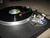
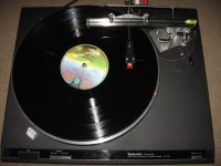
In case you thought this thread had finally run out of steam, here is a few pictures of my latest version. Compared to some of the incredible feats of machining and engineering mine is built on the KISS principle and works amazingly well.
Cheers
Graham.🙂
Cheers
Graham.🙂
Attachments
Hi Graham.
Great to see another fine arm born of this thread. Nice work, clean and simple.
Your track appears to be quite close to the record surface (a good idea in my books). Is there adequate clearance for record changing or does the whole arm pivot away from the platter, it's a bit difficult to see which from your pics.
All the best
Niffy
Hi Niffy
The tracks clear the record surface by 20mm which is just enough to easily change records. I purposely wanted the contact point with the bearings to be as low as possible to reduce the operating angle to the stylus. Sorry for the crappy photos.
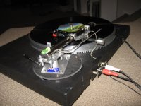
Although the consensus seems to be that glass tubes work best for the tracks, I am getting smooth operation using highly polished stainless steel tubes.
Cheers
Graham
The tracks clear the record surface by 20mm which is just enough to easily change records. I purposely wanted the contact point with the bearings to be as low as possible to reduce the operating angle to the stylus. Sorry for the crappy photos.
Although the consensus seems to be that glass tubes work best for the tracks, I am getting smooth operation using highly polished stainless steel tubes.
Cheers
Graham
Hi Graham
I know several builds have successfully used steel which is cheaper and is definitely easier to source. I personally ran with the consensus and used glass. I did however support my glass rods between two steel tubes which I damped by filling with low modulus silicon sealant. Did you damp your rail? I personally think it's well worth the effort sonically.
Niffy
Yes I damped the steel tubes with rolled up cardboard inside. I don't favour the ultra short arms that some are using as I feel that will create problems with VTA on less than perfectly flat records. From bearings to stylus is 90mm and the bearings are 75mm apart. Works for me !!
Cheers
Graham
Cheers
Graham
- Home
- Source & Line
- Analogue Source
- DIY linear tonearm