I counted ten bearings. Not feasible.
Re vectors, very sketchy: The friction force exerts a clockwise torque through the orange lever arm on the rhombus, on the other side exerts a torque on the two levers indicated in brown what results in a counterclockwise torque.
The sum of the torques is zero.

Re vectors, very sketchy: The friction force exerts a clockwise torque through the orange lever arm on the rhombus, on the other side exerts a torque on the two levers indicated in brown what results in a counterclockwise torque.
The sum of the torques is zero.

Carlo,
I got my toy made. This thing is fun. The question of cartridge angle occurred to me and the only solution I found was some kind of guide parallel to the track of the pivot. It could be a bar and magnet or, and this is ironic, a V trough and a bearing or two.
I think the rest of the bearing complement could be reduced to four mechanical at the outside corners and three string/magnet for the control arms.
Doug
The problem with magnets for control is that the lateral force is zero when the magnet is in the planned place. A restoring force will be generated only when the lateral displacement is above zero (that means, that there is a deviation from the geometry).
Axial force and lateral force one coaxial magnet pair with axial gaps x of 5.5 and 6.5 mm
Axial force and lateral force one coaxial magnet pair with axial gaps x of 5.5 and 6.5 mm

... meanwhile
Well, seems that the topic #4947 for a no-wheels LTA interests just me and a few others.
In the absence of the indispensable detailed analyzes by qualified members, I fiddled with freeware simulation programs and their known limitations, checking some previous ideas. As feared, things are quite complex, more complex than previous simplistic assumptions would imply
Summarizing the results:
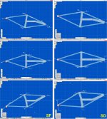
The headshell alignment remains the biggest technical problem: on the drawings the split geometry seemed effective, but wrong in the test with the dedicated mockup - unfortunately the only solution seems for now to be the dual geometry.
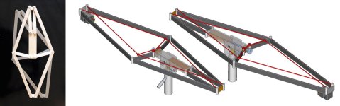
attachment 1 - this is what could be like if those levers could be strings or thin rods. Just a sketch, not a design.
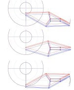
The dual geometry tested in Linkage2 looks completely correct, following a perfectly linear path.
attachment 2 -3
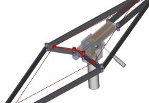
The simulations in Algadoo were somehow reassuring: the vector breakdown is obviously complex and variable with angle, but the advantage levers minimize the friction effects on bearings, as on a PTA. SF forces during rotation are distributed quite correctly and evenly; Even if the SD contribute is very low, it's action seem quite uniform for the whole rotation, without the opposite skating effects previously guessed.
attachment 4
so, ending - unfeasible? not for every skilled complicated chronograph diyer
ciao - carlo
the design and simulation files are obviously at disposal of anyone interested
Well, seems that the topic #4947 for a no-wheels LTA interests just me and a few others.
In the absence of the indispensable detailed analyzes by qualified members, I fiddled with freeware simulation programs and their known limitations, checking some previous ideas. As feared, things are quite complex, more complex than previous simplistic assumptions would imply
Summarizing the results:
The headshell alignment remains the biggest technical problem: on the drawings the split geometry seemed effective, but wrong in the test with the dedicated mockup - unfortunately the only solution seems for now to be the dual geometry.
attachment 1 - this is what could be like if those levers could be strings or thin rods. Just a sketch, not a design.
The dual geometry tested in Linkage2 looks completely correct, following a perfectly linear path.
attachment 2 -3
The simulations in Algadoo were somehow reassuring: the vector breakdown is obviously complex and variable with angle, but the advantage levers minimize the friction effects on bearings, as on a PTA. SF forces during rotation are distributed quite correctly and evenly; Even if the SD contribute is very low, it's action seem quite uniform for the whole rotation, without the opposite skating effects previously guessed.
attachment 4
so, ending - unfeasible? not for every skilled complicated chronograph diyer
ciao - carlo
the design and simulation files are obviously at disposal of anyone interested
Attachments

Neither lever could be substituted with a string.
The vertical motion of the cartridge remains unsolved.
The vertical motion of the cartridge remains unsolved.
The vertical motion of the cartridge remains unsolved.
In what sense? As I said the cartridge alignment is perfectly obtained, but only with a twin complete Peaucelliers cells (at least I have not found anything easier).
If this mechanism could be partially made with inextensible string (dyneena) levers should be verified with a mockup built with very tight tolerances. I had tried at the beginning to make a single P mockup with stringed rear levers, but it worked just with limited angles.
I was interested in understanding this geometry, a real challenge for LTA builders; including cartridge alignment and forces distribution; design and construction seems so problematic that I gladly leave it to others much clever than me.
My "legacy" for them is that with this fascinating geometry there is a favorable leverage of >15 cm as on pivoted ones, which is always better than the unfavorable one (even if a bit shorter) of the usual LTAs, and even the zero leverage, of the Radial TAs that I like so much, you know.
c
Again: how do you envisage the VERTICAL (not the horizontal) movement of the cartridge?
Some levers can be left out as I proved with my simulation but the remaining cannot bu substituted with strings.
Some levers can be left out as I proved with my simulation but the remaining cannot bu substituted with strings.
Maybe if you looked carefully at my drawings you would save me a lot of words.
Although - as specified - it is only a sketch and not a design, it contains the answers to your questions. The problem is not the vert. articulation, very easy to achieve, but a possible variation of the CW due geometry shape variation. I made measurements and some hypotheses on how to manage it
The graphs i've posted are all i can say about this topic. Stop
c
Imho your "simplified" solution leaves some degree of freedom - to verify it on a mockup would be much better than claims
Attachments
I analysed the linkage and found no part in which only tension (pulling force) is awakened.
All are alternately used to transmit pushing and pulling forces:
Sorry for bothering you. Will not happen in the future.
All are alternately used to transmit pushing and pulling forces:
Sorry for bothering you. Will not happen in the future.
Sorry for the rude answer Alighiszem, but the vertical articulation is the least of the problems of this geometry, and the drawings seemed very clear to me.
No questions (or solutions) instead by anyone on cartridge alignment - CW way of variation, structure geometrical center (s?) etc. etc.
String vs rigid levers: surely you are right for a single Peaucellier but in the case of a twin closed structure some hope still remains because strings acts in parallel with rigid levers. That's why the idea of opening and de-symmetrizing the structure doesn't convince me.
But it would take a good proto, starting from effective triple bearings, to answer
ciao carlo
have you tried a mock up of your belted 3 pivots? - looks promising
- Home
- Source & Line
- Analogue Source
- DIY linear tonearm