I would like to clarify that my interest in these geometries is purely theoretical.* A new possible path of research after all those rails and carts of every kind.
Maybe it will be impossible to get useful practical results, but the problem itself is intriguing, and far from easy to explore.
Years ago I attempted a vector breakdown of Birch PLTs, and the matter seemed so complex that no one got their hands on such topic. This one seems even more complex (you are absolutely right Warren, and there are even worse obstacles). **
But the Peaucellier mechanism is simple and ingenious, it is no coincidence that it took two millennia from Euclid onwards. And after all, even watches are mechanical nonsense, yet they have managed to make them work, and not badly.
So it would be better to intervene clarifying our own proposals or criticisms in detail, possibly with the support of graphics. (starting with me)
carlo
*I have never been interested in building the "best arm in the world", but in expoloring, understandig these matters. After >15 working tonearms of all types now I doubt that, with the weak tracking forces, could be build a "good tonearm" with more than two pivots and 4 bearings. My favorite TA remains still a simple unipivot, with a mass distribution carefully tuned over years.
** Stylus drag misunderstanding: I must be a victim of it, because for me in a linear tracker the Stylus Drag is completely dissipated on the orthogonal rail constraints (wheels)
Last edited:
nocdplz
You are right that it should be tried in practice, much seems unfeasible and even delusional, but in the process of putting it into practice it turns out that it is quite workable.
Our job here on the forum is to do something in practice and prove its performance.
In this case, much depends on the quality of all materials and assemblies, a large number of joints and axes will cause backlash, it should be borne in mind.
Also the design is not fully disclosed, will there be a weight behind or the needle will be pressed by a spring.Large mass of moving parts will cause excessive axle friction, as it will work on the fracture.
hi Alighszem.
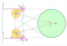
following your description I tried to make this skethc to better understand how, and if it works. If it's correct you may clarify it better than me
p.s - for me - geometrically - it works - my congratulations again
hi Havun
quote what you say - i'm an hobbyist as you and i like to build my contraptions: but before i like to design them, ie to understand well how they work
Here we have to check if these geometries can move not only with just the Side Force, as usual LTAs. How to build comes, eventaully, later. (i've already done some designs, solving cw balance etc but, as said on the first post, now could be distracting)
Attachments
Last edited:

Please see the image.following your description I tried to make this skethc to better understand how, and if it works. If it's correct you may clarify it better than me
There can't be any skating force when the stylus can move only perpendicularly to the stylus drag.The issue I see Carlo is this has the possibility to mistrack unless the pivoting HS is coupled to the mechanism so stylus drag force can drive the system. It will also have variable skate force. Inwards at the outer groove becoming zero centrally and outwards at the inner groove.
Stylus drag force is very misunderstood. In a parallel tracking TA like Niffy's and vynuhladdict's, stylus drag force with the positive castor of the CL is what drives the carriage across the LP, like a shopping trolley wheel stays straight. This then requires very low lateral friction otherwise the CL will deflect.
You can not decompose the stylus drag force vector into perpendicular components.
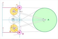
It doesn't matter. The rear end of the arm wand is a pivot. It may move sideways freely and won't be tangential to the groove. Please see the diagram. The broad red lines indicate the possible positions of the arm. As I said before, this plan won't work. It makes things complicated for nothing. This plan is already complicated enough. But it still needs extra structures and mechanisms to keep the arm wand tangential to the groove.this sketch can be clearer
distance X - Y = 0
jim - alighiszem may aswer much better - for me the alignment is determined from connection axle to single pulley and pulleys ratio. It was the same on my belt PLT Rabbit - strange devices, the pulleys ..
Last edited:
You simply do not understand the mechanism. Since the pulley D is connected to the othe pulleys, it cannot move freely.
I have never said that the pulley D will move freely, but the arm wand B.You simply do not understand the mechanism. Since the pulley D is connected to the othe pulleys, it cannot move freely.

Carlo,
I think your original drawing at 4947 can be seen as two equal and opposite twin arm PLTs with a shared wand. The rear control arm is also shared and could be built with a string, magnet, and attractor.
The genius of this is that skating becomes a positive agent as in Ralf's arm, but passive. A popsicle stick version of this might be fun to build
Doug
There can't be any skating force when the stylus can move only perpendicularly to the stylus drag.
You can not decompose the stylus drag force vector into perpendicular components.
Incorrect, skating force is created when stylus drag force is not coincident with the pivot. In Calro's arm its only coincident with the pivot at the center.
Thought I'd add a diagram to illustrate skating force. In the diaram stylus drag force GREEN acts on the imaginary point of intersection to the linear offset RED creating a torque around the pivot hence skating force.

How? Does the arm wand B "decouple" from the pulley D?...which is firmly attached tu pulley D. Why else were there the pulley D?!
Intrigued folks.........Thought I'd add a diagram to illustrate skating force. In the diaram stylus drag force GREEN acts on the imaginary point of intersection to the linear offset RED creating a torque around the pivot hence skating force.
View attachment 1187640
Can this Skating force be useful in "driving" the stylus across the radial track? - and if so it will vary from plus to minus, mid record, might it be beneficial to set the pivot outside the record and have it all the same sense, then, if so is that useful?
Eccentricities would remain a problem, driving back against it?.....
M
Not true.Incorrect, skating force is created when stylus drag force is not coincident with the pivot. In Calro's arm its only coincident with the pivot at the center.
Skating force is created when the sum of the torques caused by the stylus drag is not zero, snd this is only possible when the direction of the stylus movement is not perpendicular to the stylus drag force.
Stylus drag in green
Another example:
The wind is blowing on a zero friction car. When the direction of the wind is perpendicular to the direction the car can roll, the car will not move in either direction. But when the wind is not perpendicular, there will be a component of the force vector F dr in the direction the car can roll, and it will move.

The wind is blowing on a zero friction car. When the direction of the wind is perpendicular to the direction the car can roll, the car will not move in either direction. But when the wind is not perpendicular, there will be a component of the force vector F dr in the direction the car can roll, and it will move.
Attachments

A nice analogy.
But if the rear wheels are fixed as you've drawn (i.e. the pivot) and the front are not but can move around an arc restrained by another pivot..........then one end will move, change the fixed and partly restrained and it goes the other way?
M
I think someone needs to make a mock up soon! - not me BTW, i am still mucking around with my narrow track monkey RTA, ready soon to build another version.
First of all thank you all for your interest in these topics, it's nice to see our sleeping thread come back to life.
Your observations are all clever and correct, highlighting some problems not easy to overcome, as noted on my #4995 etc
As you say the action of the SD is favorable in the first half, neutral at the center, and contrary (!) in the second *-
therefore, #4957
So I'm thinking to design the arm with an asymmetry in order to get some inner force during the whole tracking. (old simulation based on first type Peaucellier geometry)
Or simply positioning the main pivot centered on the outer groove?
Before posting the Peucellier geometry I spent some time exploring it, with the help of a couple of creative friends.(thanks) and trying also to imagine what could be like a working TA of this kind.
Now to go further we need a detailed vector breakdown of this complex model, but my surviving notions of vector calcs are really inadequate for such task.
Difficult, without those data, to "guessstimate" if it could be feasible or not, and useless too
carlo
*Fortunately the Side Force seems always favorable, due also a long favorable lever, as on PTA
Wooden mokups already done, Doug - i can't live without, much better than the simulations i'm able to use
Attachments
Last edited:

- Home
- Source & Line
- Analogue Source
- DIY linear tonearm