That's pretty close to my total mass, a couple of grams more.Carriage mass with CW is 54g without the 8g cartridge so 62g both.
The current Vee cups are M3 setscrews radiused and polished and I have ordered some Sapphire Vee cups. The pins are carbide this time not HSS.
I found a big difference going from steel pivots and vee cups to carbide and sapphire. Greater transparency, transients and detail. Generally more immediacy. The level of friction also reduced by, if I remember correctly, 17%.
Niffy
@niffy The biggest hurdle for the Sapphire Vee's was cost of shipping. The only place I found the size I needed was in the USA and they wanted $180US for shipping plus the cost of the Vee at $5.30US each.
With my current carbide pins and M3 setscrews the force to move the carriage is 0.04g based on a total carriage mass of 62g. I didn't build a test rig I used my spare rail and shimmed the ends to determine coefficient of friction, so my uncertainty will be larger than yours.
With my current carbide pins and M3 setscrews the force to move the carriage is 0.04g based on a total carriage mass of 62g. I didn't build a test rig I used my spare rail and shimmed the ends to determine coefficient of friction, so my uncertainty will be larger than yours.
$180US for shipping! Ouch that is ridiculous, and I thought that the £60 I just had to pay for shipping on a new TT motor from Switzerland was bad.
Maybe they misread the product weight as kilograms rather than micrograms.
Maybe they misread the product weight as kilograms rather than micrograms.
Maybe just ask them to post it, no courier etc, we have recorded delivery post, international tracked and signed <£10.........
Missed this @Mike56Looking at the wheel pivots i can see the threaded cup screw to adjust centering and pressure. is there any "springiness" to take up the tension on the pivot please or is it just the cupped screw adjustment?
M
It's just adjustment. With all horizontal pin pivots there must be some end shake or the pin will bind in the Vee. With this carriage and my 4point PTA there is enough mass to prevent the pin rattling in the Vee.
Thats interesting, i have an equivalent pivot at each corner of the paralelogram and i started with a similar arrangement and learnt also about the critical adjustment. i now use a rubber grommet on the end shaft to introduce a springiness to one side of the pivot, it will not move under the carriage load but gives a constant spring against the pivot end to keep close contact, and so one side for is solid for coupling purposes and the other introduces some spring on the pivot end. Many v jevels are sold with a wee spring for the same purpose.
REINVENTING NO-WHEELS
Maybe someone may remember my attempt to build a linear TA based on pivots instead of wheels + rails (page 231 from #4616 to #4635)
Hope not, given the complete failure of that hypothesis = impossible to avoid a sliding guiding movement i.e. wheel+rail.
But the other day, browsing among the actuators used in robotics, I discovered Monsieur Peucellier who, a century and a half ago first invented how to convert geometrically a circular motion into a straight one.
https://mathworld.wolfram.com/PeaucellierInversor.html
https://en.wikipedia.org/wiki/Peaucellier–Lipkin_linkage
a real genius, maybe known to all of us except me
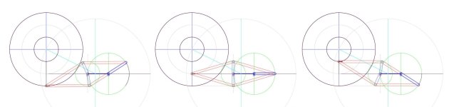
I began to think if that geometry could be right for us by testing some linkage2 simulations, and the premises are there, especially for this variant of the Peucellier mechanism, but of course may also be guessed a lot of problems:
I'd be curious to know your opinions before annoying with my first design hypotheses
ciao - carlo
Maybe someone may remember my attempt to build a linear TA based on pivots instead of wheels + rails (page 231 from #4616 to #4635)
Hope not, given the complete failure of that hypothesis = impossible to avoid a sliding guiding movement i.e. wheel+rail.
But the other day, browsing among the actuators used in robotics, I discovered Monsieur Peucellier who, a century and a half ago first invented how to convert geometrically a circular motion into a straight one.
https://mathworld.wolfram.com/PeaucellierInversor.html
https://en.wikipedia.org/wiki/Peaucellier–Lipkin_linkage
a real genius, maybe known to all of us except me
I began to think if that geometry could be right for us by testing some linkage2 simulations, and the premises are there, especially for this variant of the Peucellier mechanism, but of course may also be guessed a lot of problems:
- keeping the orthogonality of the headshell, perhaps obtainable by splitting in halves the rhombus
- the number and even more the type (the triple ones!) of joints/bearings needed
- etc- etc - etc
I'd be curious to know your opinions before annoying with my first design hypotheses
ciao - carlo
Attachments
Last edited:
I feel it may be simpler for the joints and offers some easier alignments?
https://en.wikipedia.org/wiki/Sarrus_linkage
https://en.wikipedia.org/wiki/Sarrus_linkage
Really clever, Alighiszem - congrats.
At first sight i thought back to my old Rabbit - pulley PLT, wich followed the Thales circle, while this is really a true linear TA.
However, i'm in doubt if that long wand lever isn't too unfavorable to work properly.
Couldn't the pulley train be mirrored, in a way to limit the distance from the head shell, maintaining the pulleys ratio?
Have you already tried to build it?
carlo

Thank you!
The parameters can be changed in a broad range.
This was just an example.
The wand can be shorter, the pulleys can be mirrored...
The parameters can be changed in a broad range.
This was just an example.
The wand can be shorter, the pulleys can be mirrored...
Very interesting this variant too.
I'm trying to better understand how the first one works, because the Side Force seems to counteract somehow the appropriate rotation of the pulleys: so limiting the torque at most becomes important.
One of the things intriguing about the Peaucellier is that, when properly positioned, it can use the Stylus Drag to trace much like a Birch PLT.
c
I understand your 'gut feeling' but since the main wand does not rotate, the "side force" can not counteract.
The Peucellier can not use the stylus drag since the direction of the stylus drag is perpendicular to the movement of the stylus.
This is just another gut feeling.
The Peucellier can not use the stylus drag since the direction of the stylus drag is perpendicular to the movement of the stylus.
This is just another gut feeling.
Peaucellier - I wish it were as you say - the cantilever is aligned with the stylus drag, but the TA main pivot is not - it's only aligned when the rhombus is centered.
So, as Ray would say "there is skating" or, at my hoping,: if you know how to use it, there is a tracking movement with very little side force
3 pivots LTA. - I'm trying to understand how it works, but some things are still not clear to me; with simulations it's easy to misunderstand what is the real motor of the movement (the stylus tip, as always), and get wrong bad feelings
Maybe you should have the patience to explain the mechanism in detail to me, and maybe not just for me.
c
Re: Peaucellier:
Since a vector cannot have a perpendicular component, the friction force force cannot drive the lever in a perpendicular direction.
Re three-pivots LTA:
While walking in your footsteps, I played with simulations.
The question came to my mind whether the end point of one of two rotating arms of different lengths, connected by a transmission, can describe a straight line.
The simulation showed that yes, it can.
It coud be proved mathematically, bit I let someone other do that. 🙂
It is a simple fact, I do not know how to explain it further.
Since a vector cannot...
Sorry, I can't see any differences between my Peaucellier (at the start) and a common Pivoted one: same offset angle between groove and eff length. = same skating force. (their component)
So I'm thinking to design the arm with an asymmetry in order to get some inner force during the whole tracking.
3 pivots
That's what I don't understand about your geometry:
In principle the two pairs of pulleys, with their respective axes, form a sort of the two parallelograms of an old drafting machine.
However I notice that the two intermediate superimposed pulleys rotate differently: how are they connected?
If they are connected - if not, what maintains the radial tracking beyond the simple parallelism, as in drafters?
carlo
.... seems that strange geometries only interest us two...
Attachments
There is a pivotal (pun intended) difference between your Peaucellier and a common tonearm: the common tonearm"s movement is not perpendicular to the friction force, the angle is less than 90 degrees. The fiction force vector does have a component in that direction.
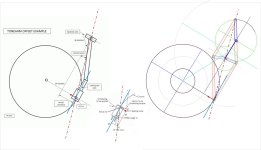
The superimposed - as you call it - pulleys function as follows (version 2.0):
The green (big) pulley is static. It is in connection with the amber pulley whish is firmly attached to the amber wand.
The turquoise wand is firmly attached to the (smallest pulley) at it's end which is connected to the purple pulley at the end of the tonearm.
REINVENTING NO-WHEELS
Maybe someone may remember my attempt to build a linear TA based on pivots instead of wheels + rails (page 231 from #4616 to #4635)
Hope not, given the complete failure of that hypothesis = impossible to avoid a sliding guiding movement i.e. wheel+rail.
But the other day, browsing among the actuators used in robotics, I discovered Monsieur Peucellier who, a century and a half ago first invented how to convert geometrically a circular motion into a straight one.
https://mathworld.wolfram.com/PeaucellierInversor.html
https://en.wikipedia.org/wiki/Peaucellier–Lipkin_linkage
a real genius, maybe known to all of us except me
I began to think if that geometry could be right for us by testing some linkage2 simulations, and the premises are there, especially for this variant of the Peucellier mechanism, but of course may also be guessed a lot of problems:
- keeping the orthogonality of the headshell, perhaps obtainable by splitting in halves the rhombus
- the number and even more the type (the triple ones!) of joints/bearings needed
- etc- etc - etc
I'd be curious to know your opinions before annoying with my first design hypotheses
ciao - carlo
The issue I see Carlo is this has the possibility to mistrack unless the pivoting HS is coupled to the mechanism so stylus drag force can drive the system. It will also have variable skate force. Inwards at the outer groove becoming zero centrally and outwards at the inner groove.
Stylus drag force is very misunderstood. In a parallel tracking TA like Niffy's and vynuhladdict's, stylus drag force with the positive castor of the CL is what drives the carriage across the LP, like a shopping trolley wheel stays straight. This then requires very low lateral friction otherwise the CL will deflect.
Both ideas won't work because there is no guiding mechanism to ensure the wand is tangential to the groove not to mention all the pivots and wheels. It is completely unnecessary. If you want to go to point A from point B, just take the shortest route.Thank you!
The parameters can be changed in a broad range.
This was just an example.
The wand can be shorter, the pulleys can be mirrored...
- Home
- Source & Line
- Analogue Source
- DIY linear tonearm