Reducing belt tension contributes as well.
I feel other factors are masking any further learning in this area at the moment now.
I feel other factors are masking any further learning in this area at the moment now.
I feel i have adressed the motor noise for now and learnt something.
I tried a lightweight platform of 3" expanded polystyrene sheets thinking LF would not go through it.
At the same time i tried two set ups, all belt off motor only
1. on polystyrene
Motor off = 582
Motor on on 33 = 583
Motor on on 45 = 584
2. on inner tube platform
Motor off = 585
Motor on on 33 = 586
Motor on on 45 = 587
So the inner tube platform stays under the motor and as i dont use 45 its ok, but what is happening at 45 there?
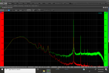
I have run a measure playing the 1khz tone and the 23hz is negligible after playing belt tensions, but the LF noise is up to within 30db of the signal peak and was lower, 35-40 down?
Mike
I tried a lightweight platform of 3" expanded polystyrene sheets thinking LF would not go through it.
At the same time i tried two set ups, all belt off motor only
1. on polystyrene
Motor off = 582
Motor on on 33 = 583
Motor on on 45 = 584
2. on inner tube platform
Motor off = 585
Motor on on 33 = 586
Motor on on 45 = 587
So the inner tube platform stays under the motor and as i dont use 45 its ok, but what is happening at 45 there?
I have run a measure playing the 1khz tone and the 23hz is negligible after playing belt tensions, but the LF noise is up to within 30db of the signal peak and was lower, 35-40 down?
Mike
Attachments


Didn't we cover the speed as the issue back in February? This conclusion had already been reached. no?
That's absolutely correct thanks Soundblaster, last time it was evident that changing the speed changed the frequency in proportion, what i didn't find was a solution to it.
So i tried hard at isolating the motor pod, but with moderate success, now i have found the motor mount adjustments make a much greater effect and en route learnt something about isolation and puzzled myself about a few other things like why the peak when using 45rpm remains high.
Best to all
Mike
I shall soon attempt to get back on topic and improve my arm some more!
The cart is currently unnecessarily long because it started life needing to spread the balls apart from the centre of mass. i might try shortening it which will stiffen and reduce mass. it will probably turn out to have some unwanted side effect from my experience!
Hi Mike,
I believe that the Origin Live decks are designed specifically to have both the motor pod and the deck mounted on the same solid surface. Putting an extra compliance under either one or separate compliances under both could result in a rotational oscillation due to a torque reaction. (Standing both motor pod and deck on an isolation platform together is a good idea).
It is possible that adding separate isolations might exacerbate the motor breakthrough problem rather than reducing it especially if the natural frequency of the isolation + motor/deck is close to the rotational speed of the motor.
If the AVMs are quite stiff it is also possible that the natural frequency will be higher in frequency and could explain the +/- 70hz side-bands you are seeing .
Rotational oscillation due to this type of torque reaction is a problem that has plagued suspended turntable designers for years. There have been many attempts to counter this problem. Many manufacturers give up and just over damp the suspension which gets rid of the torque reaction oscillation but also gets rid of most of the benefits of the suspension. I believe that Origin Live has a suspension system based on a leaf spring that only operates vertically and so cannot be induced into rotational oscillation. Definitely one of the better solutions to the problem.
There are some wacky solutions like the Kronos with its counter-rotating platters. Wacky but apparently it sounds really good. There are the very inelegant solutions like using the tonearm cable to strap the sub-chassis to the plinth. Yes Linn I'm looking at you. And then there are the counterintuitive solutions like mounting the motor on the sub-chassis. Sounds crazy but as soon as you start using the sub-chassis as your reference point rather than the ground the physics all make sense. Thank you Pink Triangle for that inspired jem.
Anyway, back to designing ingenious tonearms.
Niffy
Thanks Niffy and all you folk who keep giving me further insights to this fascinating hobby.Hi Mike,
1. Standing both motor pod and deck on an isolation platform together is a good idea
2. If the AVMs are quite stiff it is also possible that the natural frequency will be higher in frequency and could explain the +/- 70hz side-bands you are seeing .
3. I believe that Origin Live has a suspension system based on a leaf spring that only operates vertically and so cannot be induced into rotational oscillation. Definitely one of the better solutions to the problem.
4. Sounds crazy but as soon as you start using the sub-chassis as your reference point rather than the ground the physics all make sense. Thank you Pink Triangle for that inspired jem.
5. Anyway, back to designing ingenious tonearms.
Niffy
By chance i did the same degree as Mark Baker of OL, We both studied Ship Science at Southampton, no idea where that note leads!
1. i will revert to that and measure now i have retuned the motor mount and belt
2. What please are AVM's, anti vibration mounts is my guess?
3. Yes, OL use the leaf spring and i admire their work, that's probably why my wife cannot understand after we both went to the factory i am now playing around with other things! - but its fun isn't it!
4. Can you give a slightly deeper insight there, as i will eventually expand the project to include TT
5. Indeed, new rail experiment soon and cart revision to follow, hopefully i can gain input as those come along
Best to all, Mike
Damping and mass
Super10018, Niffy, and anybody else who uses Aluminum,
This is a nice lead in to a question I've been meaning to ask...
I see lots of very impressive work using Aluminum. Here's just one example by Niffy -
https://www.diyaudio.com/forums/att...02d1474197899-diy-linear-tonearm-imag0456-jpg
I've seen several others, but hard to find in this big thread.
Is there a usually a need to damp Aluminum for the best sonics?
I'm thinking my next LTA may use Panzerholz (well damped) to support the Carbide rails. Does anyone have any experience to suggest whether this is a good idea?
Hugh
Hi Mike,
First, usually, a heavy carriage does sound better.
Jim
Super10018, Niffy, and anybody else who uses Aluminum,
This is a nice lead in to a question I've been meaning to ask...
I see lots of very impressive work using Aluminum. Here's just one example by Niffy -
https://www.diyaudio.com/forums/att...02d1474197899-diy-linear-tonearm-imag0456-jpg
I've seen several others, but hard to find in this big thread.
Is there a usually a need to damp Aluminum for the best sonics?
I'm thinking my next LTA may use Panzerholz (well damped) to support the Carbide rails. Does anyone have any experience to suggest whether this is a good idea?
Hugh
Hi Mike,
Yes, an AVM is an anti-vibration mount. The term can cover many different types of mount, springs, sorbothane, cork, washing machine footers etc.
I will endeavour to expand on my making the sub-chassis the reference comment when I get a chance. It will probably require quite a long post to explain it properly
Niffy
Hi Hugh,
I definitely agree with Jim that a heavier carriage (or at least one with high lateral effective mass) sounds better.
Vertical effective mass still needs to be kept at a more normal level.
Increasing carriage mass by just adding weights is not the way to go. The additional mass should ideally also add to the rigidity of the carriage. My carriage is made from carbon fibre and balsa wood cores in order to maximise the mass to rigidity ratio.
I have used aluminium extensively in the construction of both the deck and the arm's main support structure. The rail itself being several different grades of steel, carbon fibre and tungsten carbide.
The shape of a component is as important as the materials it is made from. A solid lump of aluminium will be pretty inert and won't require extra damping, such as my suspension towers that are 50mm in diameter and only 63mm long.
The large flat structures are made from two pieces of 5mm aluminium sandwiching 20mm of acrylic. A 5mm piece of aluminium of this size will ring like a gong. Just apiece of acrylic would not be rigid enough. A sandwich structure, as I have used, is incredibly rigid and much more dead than either the aluminium or the acrylic by them selves. The deck also has an aluminium and lead sandwich counterweight built into the lower section of the plinth that acts as a sink for vibrational energy from the sub-chassis.
Niffy
Hugh, Jim, Niffy,
Interesting thoughts going in this thread.
Weight, stiffness, geometry, arrangement are all of interest to me at the moment.
I now have an arrangement that works quite nicely and is quite tolerant.
The latest is with anodised aluminium rails in vertical orientation with Pen tip pivot paralelogram. So moving true linear in both planes.
Having tried lots of configuration options to get to here i will develop this with small adjustments in geometry and construction.
For materials i use those i feel might be right and i can work with hand tools easily. Aluminium beats carbon sheet hands down in this respect because of its homogeneous nature, drill a carbon plate and hit some tows and the drill is off sideways, but various physical properties of the carbon plate are much better than aluminium. at this point i cannot comment as a materials scientist or vibration engineer so just try to use an engineers intuition and feel.
Another point of interest to me is whether to make components longer or shorter, for example i could shorten the paralelogram levers but that takes away their mechanical advantage, i could shorten the carriage rails as their is a blind centre between balls, which might be better, again i tend to experiment and measure following intuition rather than pure science.
Best
Mike
Niffy, Thanks for that reply and posting all that great work!
Mike56, Looking forward to seeing what you come up with.
Hugh
Mike56, Looking forward to seeing what you come up with.
Hugh
Hello, I’ve not checked in on this thread fir a while.
I have made the original version of this arm. I’m playing around with different bearings. I have found a few bearings that work in as much as they don’t skip at all and track well. The issue I have is the cantilever has a sort of ‘drag’ . The record grooves moves one way or the other, the cantilever then moves and then there is a slight delay whilst the bearings catch up. The other Tonearm I have is air bearing linear and clearly with this there is no ‘drag’ it reacts immediately. My query is this. Is a certain amount of flex in the cantilever within tolerance, doesn’t affect the sound quality. I know compliance etc but nevertheless is a certain amount of lateral movement ok and expected - on a pivoted arm for instance.
I couldn’t upload the video but there is a YouTube link so hopefully you can see what I’m going on about. As always, thanks in advance.
Troika stylus movement - YouTube
You're probably seeing the effects of friction relative to an air bearing AND the effects of excessive horizontal moving mass of the carriage. Think of the cantilever as a slightly stiff rope that has to drag that mass back and forth with any record eccentricity.
Thanks soundblaster. Is that within the bounds of acceptability? Or too much and I need to get lighter carriage or better bearings.
That doesn't look bad at all.. I've seen far worse. I'm not sure about the compliance of that particular cartridge but it does not seem to be putting a strain on the cantilever suspension.
That is good to hear. I have to say it sounds completely fine to my ears but I wasn’t sure how usual it was for it to flex laterally. Thanks
Lateral motion gives you mono information.. Vertical motion is what gives you difference information. If anything, you might see a lot of subsonic motion of woofer cones.. If your system has some sort of low frequency filtering, it's shouldn't be an issue.
The higher lateral mass will have little effect in terms of extra cantilever deflection. (The benefits of higher lateral mass massively outweighs any negative effects).
All of the deflection you are seeing is due to bearing friction. If you can see the cantilever deflect with the naked eye the friction is too high. The smallest definition visible to the naked eye is about 0.2mm. With a typical cartridge this will result in a +/- tracking error of about 1.15°. If the visible deflection is greater than this then the tracking error will also be greater.
I put a lot of work into reducing bearing friction in my arm. I ended up using jeweled bearings with tungsten carbide wheels running on tungsten carbide rails. The measured friction is about a quarter that seen with even the best ball race bearings which in turn have friction that is a lot less than half that of standard bearings.
I posted a video a while back showing the deflection of the cantilever of my Ortofon 2M black cartridge on a record with extreme eccentricity. The cartridge is moving back and forth by 3.2mm, much more than any playable record would have.
Lateral tracking torture test. - YouTube
Even at this high magnification barely any deflection is visible. It is possible to achieve this but it took a lot of work. My bearing system is considerably more expensive than using ball race bearings but is much cheaper than a decent air bearing. Keep working on it and you can get that friction way down.
Niffy
Thanks for the input. It really is appreciated.
Niffy I’ve used the boca bearings, first fully ceramic-which were awful then hybrid and then the hybrid with the orange seals which seem probably to be the best. I haven’t soaked them in carburettor solution yet which I intend to do. These are 4mm wide. The ones in the video I put in today, skf open bearings which are 2.5mm wide. These seem to be a tiny bit worse than the orange ones but they sounded so much better.. very strange. I’ve only played a couple of album sides I need to put the others in and do an a/b. If there is a difference then it’s either the 1.5mm width or the rubber seal doing something strange to the resonance?? Or it’s my ears. The plinth is panzerholz and split for isolation so I know plinths and materials can have an effect...probably my ears. I shall swap tomorrow.
I am interested in where you got your jewelled bearings. I’ve gone through many bearings in the uk and the USA and I’m running out of obvious options. For me, having been fiddling with this for a while now-everything really revolves around the bearings really..I made the plinth as well based on lenco. I have invested a lot of time in this so additional expense on bearings would be worth while. I very much appreciate your input. The things you create are truly impressive and motivational.
Last edited:
- Home
- Source & Line
- Analogue Source
- DIY linear tonearm