Good evening gents, and it all seemed to be going so well, (Carlo and others talked of the wrong turnings and so on!) ........so i mounted it on the arm, by which time the lower arm that holds the counterweight has sagged the Mylar hinge a touch and its clear all is not moving parallel as it has a slight spring centring action, whereas before that it was very free. Anyway i played a few tracks and unfortunately the current set up is a backward move from my BB parallelogram that sounded rock solid in pitch, this is warbly by comparison so what apparently cannot flex noticeably is doing so as things move in warp. More thinking required at this point, i still like the mylar hinge but its inexact to construct and its not carrying the weight well. The hinges might be wider to counteract those things, the counterweight split between upper and lower, the hinge shorter etc etc more experimentation now required
Well, not a total disaster after all.
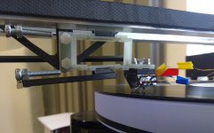
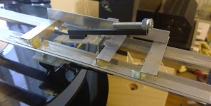
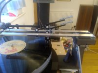
I split the counterweight and it now plays ok, I would say sounds tighter in mid and treble than old BB one, certainly not a bad player. Odd little chocks to achieve clearances I didn’t originally know were needed!
However the torques I am unintentionally imposing on the mylar hinges with my arm lift lever are upsetting them. Its not easy to see but the lever, which is quite light, goes away behind the bottom counterweight bolt and is twisting the mylar strips just with its weight, whereas the top one is not.
This has potential!
I think linked with a “Carlo carriage” and properly built this could be on target (I am not sure which one!)
Attachments
Great news Mike; once it works, perfecting everything else is just a pleasure
Leave the parallelogram only the role of managing the cartridge, it's just busy enough, imo.
carlo
"My" neanderthal carriage doesn't necessarily go any better than this one or others: maybe, with the same friction, it's just easier to build.
Leave the parallelogram only the role of managing the cartridge, it's just busy enough, imo.
carlo
"My" neanderthal carriage doesn't necessarily go any better than this one or others: maybe, with the same friction, it's just easier to build.
I still have the occasional carriage bearing stick Carlo, so non recirculating ball carriage it will eventually be, hoping to remove that problem. if i can build that and a whole arm lift at the same time i can unload the parallelogram of its lift mechanism and reduce the travel requirement as well, so lots of potential there (for mistakes as well!)
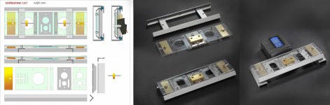
corkscrew cart proto
Used to the weight and size of the LC carriage, this instead seems to me a truck for removals, full of wobbly stuff.
To work it works, the vertical movement is achieved without effort and the "pistonic" head shell behaves without any twisting on both axis. Triacetate hinge is a bit stiff (still too springy < 0,5 gr VTF variation on a 3 mm warp) but easy to be changed with a thinner or a fabric one. The use of carbon can be beneficial, even if structure and levers weight already 16 gr, and there are 14 gr CW + 5 gr head shell that can't be reduced.
Many mods, many details to improve, as usual a lot of work to do; hoping it's worth it.
But I've not the right feelings, doubting that could be a real step beyond the Lil Casey: certainly it's not simpler, simple the way I like
carlo
Attachments
Carlo, i like lots of this and can see there are many opportunities to miniaturise and lighten, thus changing the removal truck into a sports car. I think (but am not sure, probably requires a model!) I feel happy the geometry allows pistonic movement without skidding with the pivot point below the lever arm, but am uneasy about it always remaining symmetrical. in my early cart i depended on weight keeping thigs vertical but varying forces and levers upset that when there was a cartridge imparting the forces and i see a parallel here in that one side can rotate more than the other and upset azimuth. in my case it was overhang which you identified previously, maybe performance would be more tolerant of the azimuth movement?
How can the whole be best kept on its pivots in mishandling? - a little stop above or so?
How can the whole be best kept on its pivots in mishandling? - a little stop above or so?
hi Mike: the length of the non-recirculating carriage is given by the stroke - the width by the overall dimensions of the cartridge, so there is not so much to miniaturize - using carbon we can save up to 4 grams, but the ball friction is worse than for anodized .
Pistonic effect: here the hinges are 2 mm gap - 33 mm wide, so they have a much higher transverse resistance than the tracking forces, the lever is even smaller than the thickness of the cartridge itself (the pivots are lowered) - so no twisting imo, but must be tested in real conditions.
Safety - you will notice a hole near the pivots: the seat of a thin rivet - free to move but able to prevent the levers from jumping out in case of silly maneuvers. However leverages are quite stable on their V cups.
Despite all these nice qualities, my doubts remain
carlo
Carlo, talking out my hat, as I often do, i was thinking more of parts, levers and counterweights, hinges closer to cartridge (might reduce stability?) and longer counterweight levers and lighter counterweights? best, mike
Very interesting DD, there's little new in the world!
However, as I've found its much easier to draw it than make it work, however with Carlo and others help and input i have something that works well and will be improved!
if you push translate you will find the author knows that as its an appeal for help to make one work.
However, as I've found its much easier to draw it than make it work, however with Carlo and others help and input i have something that works well and will be improved!
if you push translate you will find the author knows that as its an appeal for help to make one work.
Since I still can't find of a solution for the corkscrew cart + rail that really convinces me (or my aesthetic taste?), better to leave the project freeze for a while
Some time ago I had proposed a mousetrap tech solution (#4007) for the parallelogram*, so i had to do some checks to verify that provocation, at least with a careful mock up (or a rough proto, as you like).
Not bad at all - despite the fast construction it moves effortlessly and is decidedly stiff to flexures, while maintaining well the parallelism; the 0.3 fishing line elasticity gets the magic to keep the whole contraption working together. Those holes are there not only for lightness, but mainly to reduce hinges friction.
Indeed, now I think that, considerably reduced both in height and in width (now 30x25 x40 length) and with some improvements (eg teflon on hinges) mat become a really compact, effective device.
carlo
*Parallelograms have been around long before Euclid, applied to solve many different problems. On the Lil Casey the parallelogram works mainly as a scale, indifferent to the variable position of load (cart traveling on rail).
On a fixed rail instead is needed a parallel vertical motion, which doesn't resolve completely, geometrically the VTA problem on warps (fake, imo), as Niffy once demonstrated.
My opinion (#2695) on that Japanese parallelogram (# 2689) has not yet changed substantially. Mike's one is completely different, that's why it works.
Attachments
Last edited:
Some of you will remember i got to the point where my circular Ball race on glass rails cart carrying a parallelogram to cater for warp in line with the radial rail worked ok but with occasional skips caused by stiction of the BB’s on the glass rails.
I started with two bearings in line but the varying torques in line with the groove from stylus drag and the changing moment from warp caused a sway axially with the groove giving varying overhang and wow, it looked awful and was audibly deficient in that respect. In other respects, it sounded promising enough to warrant further work.
Polishing the rails etc helped but i eventually decided to go for a non recirculating individual ball on rail system basically like the principle Carlo uses. So armed with 5mm Delrin balls and various rails i set out to experiment.
I rapidly became aware that “hand tools Mike” could not possibly make a 4-bearing cart like Carlo’s where the 4 bearings kept contact and hence position regularly. He has far greater precision than i do.
Consequently, i thought i would replicate what i had done previously with the circular ball races, putting three individual balls on the rails so it could settle evenly between them like a 3-legged stool and cope with irregularities in the transit. I used one double V over V primary rail and an arc on V secondary rail.
That seemed to be promising but the progression of the top rails over the balls and the bottom rails was always a problem on the single ball side, the plan view centre of gravity and its moment upsetting the transit, and falling over at the end, Carlo kindly drew out what was happening and led me to a preliminary conclusion. That was to bin that concept!
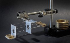
So now i have a 4 ball non- recirc cart with each rail self-aligning and height absorbing separately. This is done by treating one rail as the primary rail and allowing those two balls and their top rail to predominate and the second rail to be articulated on a pivot from that. Difficult to describe but hope the pics show and explain.
So far, with little tuning, it plays a record, no sticks, needs some refinement but a good start, more later
Thanks to Carlo and all those others who contributed to my progress so far and i look forward to much more!
I started with two bearings in line but the varying torques in line with the groove from stylus drag and the changing moment from warp caused a sway axially with the groove giving varying overhang and wow, it looked awful and was audibly deficient in that respect. In other respects, it sounded promising enough to warrant further work.
Polishing the rails etc helped but i eventually decided to go for a non recirculating individual ball on rail system basically like the principle Carlo uses. So armed with 5mm Delrin balls and various rails i set out to experiment.
I rapidly became aware that “hand tools Mike” could not possibly make a 4-bearing cart like Carlo’s where the 4 bearings kept contact and hence position regularly. He has far greater precision than i do.
Consequently, i thought i would replicate what i had done previously with the circular ball races, putting three individual balls on the rails so it could settle evenly between them like a 3-legged stool and cope with irregularities in the transit. I used one double V over V primary rail and an arc on V secondary rail.
That seemed to be promising but the progression of the top rails over the balls and the bottom rails was always a problem on the single ball side, the plan view centre of gravity and its moment upsetting the transit, and falling over at the end, Carlo kindly drew out what was happening and led me to a preliminary conclusion. That was to bin that concept!
So now i have a 4 ball non- recirc cart with each rail self-aligning and height absorbing separately. This is done by treating one rail as the primary rail and allowing those two balls and their top rail to predominate and the second rail to be articulated on a pivot from that. Difficult to describe but hope the pics show and explain.
So far, with little tuning, it plays a record, no sticks, needs some refinement but a good start, more later
Thanks to Carlo and all those others who contributed to my progress so far and i look forward to much more!
Attachments
Mike,
it's a brilliant idea to make second rail of the cart self-adjustable!
Best regards,
Rpeter
it's a brilliant idea to make second rail of the cart self-adjustable!
Best regards,
Rpeter
Thanks RPeter, its interesting isn't it? i feel it has potential, all drawn along by those who respond on here, best, mike
"So now i have a 4 ball non- recirc cart with each rail self-aligning and height absorbing separately. This is done by treating one rail as the primary rail and allowing those two balls and their top rail to predominate and the second rail to be articulated on a pivot from that. Difficult to describe but hope the pics show and explain."
I like the sound of that and I've looked at our pictures for longer than I'm willing to admit, but I can't figure out how the rails self-align. I'm not even sure which of your two rails is the predominant one. I assume that your bottom rails are fixed and that the aligning is taken care of by the uppers, but I still don't quite get the processes involved in that.
I like the sound of that and I've looked at our pictures for longer than I'm willing to admit, but I can't figure out how the rails self-align. I'm not even sure which of your two rails is the predominant one. I assume that your bottom rails are fixed and that the aligning is taken care of by the uppers, but I still don't quite get the processes involved in that.
I like the sound of that and I've looked at our pictures for longer than I'm willing to admit, but I can't figure out how the rails self-align. I'm not even sure which of your two rails is the predominant one. I assume that your bottom rails are fixed and that the aligning is taken care of by the uppers, but I still don't quite get the processes involved in that.
Good morning Grufti and apologies for my inadequate explanation, - that, in itself is not surprising as i often confuse myself before trying to explain it to others!!
The pics are not great and further confused by the fact that the cart still has three transverse members which were necesary when the cart rails were joined at the ends but are now redundant.
So, the runner rails are fixed V and V and parallel and radial at some point over the stylus.
They are extruded L's set at 45 degrees to be V's on a jig, by putting them upside down either side of a spacer block, so they are as parallel as the extrusion and the block, i then just glue end plates to them and there i have runner rails as parallel as hand assembly will allow.
The cart rails are also V and V, in fact a section taken to the grinder wheel and both edges ground off.
Both are sanded flat with 1200 and polished with compound.
Once again this is made by eye to the best accuracy i can, it is all certainly within tenths of a mm but unlikely better than that, and will vary with temperature etc. Not much but enough to upset the perfect contact of 4 balls at 4 points, 16 contact points.
First off, i attached these cart rails parallel to the cart rigid and tried the mechanism first with 4 balls. Pushed by hand i found the contact inconsistent unless i flexed the cart with excessive weight to maintain constant contact on all 4 balls. I never set it to work because i didn't like the inconsistency.
I then concluded that i could use two balls on one rail and one on the other and like a three legged stool it would always have three feet on the floor or in this case maintain constant contact on all three balls.
It did that, but because3 the balls move relative to both sets of rails and the centre of gravity of the cart is fixed relative to the cart, at the ends of the travel the plan view of the centre of gravity moved outside the triangle formed by the three balls, another failure.
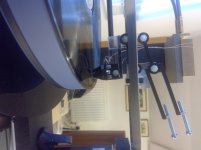
So now i have taken that same cart and i treat the stylus side as the dominant side and the whole cart is rigid on that side, effectively a two ball cart with V on V, so as it runs one ball can rise and fall or move in any other direction freely relative to the other, thus maintaining perfect contact under gravity. By the way, yes, these tiny movements reorientate the cart slightly as they happen but the effect is tiny.
Now to your question! - so the subsidiary rail (non stylus side) is now attached to the cart only on the ball bearing you see in the picture that isolates it and allows rotation in the vertical plane along the rail and through its play in every other direction as well. Look carefully and you can see that the two end transverse members of the cart are not now attached to the rail, they will be cut away at some point in development which would make it much more obvious.
Its analogous to a car with one fixed axle and one suspended axle, but as it moves very slow doesn't suffer the damping problems such a car would suffer.
I hope all that helps, i will take better pics at some point, mike
Good evening all,
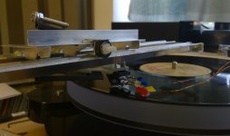
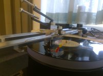
After much thought provoking input from Carlo in particular and Karsten as well and other posters, thanks to all, i now have playing my radial rail non recirculating BB cart with self adjusting secondary rail and zero horizontal torque parallelogram.
Its been cut about and rebuilt so many times it looks tatty but so far plays well.
The set up gained some Azimuth and VTA adjustment potential en route as i cut and bolted things together.
The total of all moving parts is 44grams, cartridge included.
I didn't rebuild with Mylar in the parallelogram yet because its so much easier when experimenting to use nuts and bolts.
There is scope to take a third out the weight and miniaturise it all, but i am quite exhausted by it all at the moment!
So far, i think it sounds good, detailed and clear, really tuneful bass, nice percussion, piano etc.🙂
Some pics attached, interested in your feedback!
Best mike
Attachments
Hi all,
Maybe Mike is too modest, if he had followed my "expert" advices he would still be at square one; instead after the transverse parallelogram he invented the torsion carriage to compensate tolerances, and now he has already in mind a new compact solution, practically without negative levers.
I'm afraid that from the photos and descriptions, the importance of Mike's work is not well understood: this is the first arm authentically, completely linear - the traditional ones are only at half.
What's around of more simple? it is the solution that any person would think at first of to trace a disc, "like the lathe that recorded it" ,as the sellers say. Too bad that this solution has been considered unfeasible by experts and builders for more than a century.
We should take note of this, in this thread dedicated to linear passives.
Lil Casey pioneered the path of the radial rail, and this, with its parallelogram, looks like a son or a brother, but it is not at all, and contains two radically different ideas. much simpler and more rigorous.
One thing I do not forgive my friend Mike: that after my provocation of the corkscrew cart #3762, having seen his solution at work (congratulations), now I have to build it ...
carlo
already at the 2nd prototype :-(
Last edited:
Good morning Carlo and thanks for your appreciative words, one thing which is great fun as well as invigorating, intellectually stimulating and enormously helpful is that with your intellect experience and skills, you (and others) understand what i am doing and making almost before i have done it, and give your inputs, its the beginner at work in a complete design team, all greatly appreciated, mike
- Home
- Source & Line
- Analogue Source
- DIY linear tonearm