Busy to finish and match this stuff, I missed 10 discussion pages. I didn't think the corkscrew gadget could stimulate so much creativity, I will study all carefully.
Only one tip dictated by experience: keep it simple, friends. We are working on a minefield, friction > 2-3 mN begin to be problematic: little weight, few joints, less bearings (linear ones? no thanks) are the starting point
carlo
in the meantime, congratulations to Warren for the successful improvements: Great !
We will be intrigued to read your thoughts backed by experience, just as with all the others. its great to have such inputs as a newbie.
I have now ordered enough bits to make what i scribble/sketched at my previous post, so I will build something like that as a start point soon now.
One thing that always intrigues me Carlo is how the ball bearings stay correctly positioned between your two rails and don't skid occasionally? mike
I think you will find the drag on the stylus will cause pivoting of the bearings on the rail.
Carlo used a small CW in front of the cartridge to counter this force.
Well, not exactly*.
the small CW balances just the cartridge weight, to level perfectly the VTA and load vertically the carriage, so as to minimize friction and facilitate its self-centering. (static setup)
The stylus drag**, as known, has an average value due the VTF + tip shape, and a variable one due the musical content - peripheral speed, etc. in order of importance. Minimizing the lever, these tilting forces are very modest, almost undetectable even during the touch down of the tip on the disc. (widely discussed in the past, and showed by a video)
So what does the dynamic setup I talked about, consist of? to tune a minimal underhang (1.5 mm in the worst case) in order to maintain dynamically the correct leveling for that cartridge+VTF, so that self-centering has to manage only the SD variations (<30%).
Simple, but not too simple
carlo
* the contribution it provides is only due the inertia: someone will have noticed (photos and measurements on drawing) that LC uses a very low weight, but at a distance to increase its eff mass.
** on Angling for 90° thread I measured with a pendulum an SD much lower (1/4 ca) than what is calculated with the formulas, or indirectly with the "stopping down method".
* the contribution it provides is only due the inertia: someone will have noticed (photos and measurements on drawing) that LC uses a very low weight, but at a distance to increase its eff mass.
My "Design"+copying+sketch/scribble will no doubt need to evolve, right now i am following early advice to "build something and see"/get a real life feel for it, but trying to avoid as many wrong turnings as possible.
I perceive each poster has a style of thinking and process, some no doubt much more scientific than mine, but for this question i have a light carriage but with some weight available on the parallelogram to do the balancing/inertia written about.
I will centre the stylus under the rails geometrically and leave the weights a touch forward of that initially and hope the balance is correct. I have a small counterbalance weight on the parallelogram already and will swing this away or closer to the rail in a plane parallel to the platter to achieve balance. i have ordered a selection of light nylon nuts and bolts to allow for such experimentation by unbolting and replacing parts.
Thanks again
Mike
Nylon is not particularly strong. Polycarbonate is somewhat stronger.
RENY or PEEK offer substantially greater tensile strength for a given bolt diameter, and for a given strength, these materials will enable a reduction in bolt diameter and mass.
RENY Search results | MISUMI online shop - Select, configure, order
PEEK Search results | MISUMI online shop - Select, configure, order
Plastic & Ceramic Screws - Screws & Bolts | MISUMI
Plastic & Ceramic Screws - Screws & Bolts | MISUMI
Nylon is not particularly strong. Polycarbonate is somewhat stronger.
RENY or PEEK offer substantially greater tensile strength for a given bolt diameter, and for a given strength, these materials will enable a reduction in bolt diameter and mass.
Many thanks for those thoughts and links.
I am going to start with cheap and simple and update if it works, hence the fastening choice, i looked at peek but didn't find a suitable supplier, so thanks for that, mike
Why not use aluminium bolts to keep weight down. Also drill holes in any bars to reduce weight, just make the holes non-uniform.
For fastener applications where both weight and strength are issues, I usually choose RENY over aluminum. 7075 has approximately twice the tensile strength of RENY, but about twice the density; therefore using RENY allows larger bolt diameters, benefitting stiffness.
Torlon 5030 is also worth considering for applications demanding both lightness and strength, but at substantially elevated costs.
PEEK GF30 (30% glass fiber), density 1.53g/cm³, tensile strength 113MPa
PEEK glass fibre reinforced - TECAPEEK GF30 natural | Ensinger
RENY 1002H (30% glass fiber), density 1.46g/cm³, tensile strength 220MPa
https://www.m-ep.co.jp/en/pdf/product/reny/physicality.pdf
Torlon 5030 (30% glass fiber), density 1.61g/cm³, tensile strength 221MPa
https://www.solvayultrapolymers.com/en/binaries/Torlon-PAI-Design-Guide_EN-227547.pdf
Aluminum 7075 density 2.81g/cm³, tensile strength 540MPa
https://www.smithmetal.com/pdf/aluminium/7xxx/7075.pdf
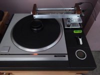
Was playing again today with the LTA. Used the HFN test LP to check tracking and I did not expect to see the stylus skate across the LP on the tracking ability test side 2 band 1, The only way I could get it to track was 2.5g VTF, the reference EPA100 tracked this at the 1.5g which is at the top of the VTF for the ECP205.
I can still hear distortion on heavily modulated tracks and distortion changes channel on off centre pressing, because the arm sounds so good this distortion is very obvious on SOME LP's
Damn this LTA has no right sounding so good.
Plan 1 - Rebuild the original LTA but increase the diameter of the arm wand to 8mm instead of 6mm. Was this LTA just not detailed enough to hear the distortion or was it missing as the carriage is so much lighter?????
Plan 2 - If 1 works build a new lighter carriage for the bridge LTA still using pin bearings. I have some ideas here but will wait for the results of 1 first.
Attachments
Why not use aluminium bolts to keep weight down. Also drill holes in any bars to reduce weight, just make the holes non-uniform.
For fastener applications where both weight and strength are issues, I usually choose RENY over aluminum.
Many thanks for further input gents, always very useful, i am beginning to collect these bits now for my first LTA, i am expecting the whole vertical mass to be less than 25 gramms and the horizontal less than 35, this seems reasonably light to me, revelation will be;
a) when i first hear it
b) when i weigh it
Now, yesterday it was raining hear and i was looking at ideas, came across this attachment which shows the parallelogram on the carriage idea has been drawn before in a different arrangement, couldn't find evidence of build but interesting as always.
Today i will try to glue up my con rods...........
mike
Attachments
Hi Mike - this topic was previously discussed - Walter (look at #2689) pointed out to me that solution (I doubt ever made ) shortly after the realization of the Lil Casey MK1. My opinion #2695 has not changed substantially. even now that i'm building the third one
carlo
together with weights, friction has a great importance
carlo
together with weights, friction has a great importance
Have you considered filament or flexure bearings for the vertical bearing? Simpler, lower friction, less noise and chatter.
AMG Tonearm Details | Analog Planet
https://www.thevinyladventure.com/wp-content/uploads/2018/11/amg-12j2-tonearm02.jpg
(Vertical bearing consists of two 0.5mm thick spring steel wires)
A New Project
AMG Tonearm Details | Analog Planet
https://www.thevinyladventure.com/wp-content/uploads/2018/11/amg-12j2-tonearm02.jpg
(Vertical bearing consists of two 0.5mm thick spring steel wires)
A New Project
My reaction to these kind of bearings , as well as the Schroeder tonearm, is that there seams not to be a very good mechanical grounding through these bearings . I like as rigid a connection as possible from cartridge body to mechanical ground. I could be very wrong, though.
Have you considered filament or flexure bearings for the vertical bearing? Simpler, lower friction, less noise and chatter.
AMG Tonearm Details | Analog Planet
https://www.thevinyladventure.com/wp-content/uploads/2018/11/amg-12j2-tonearm02.jpg
(Vertical bearing consists of two 0.5mm thick spring steel wires)
A New Project
Ah! Korf Audio! I was racking my brains trying to remember where I'd seen it.
Wouldn't more deflection = more resistance though? Not a massive issue with a conventional arm because of the lever length, but on a very short arm it could be more significant when tracking warps.
A stiffer flexure would allow you to set tracking force by twisting the flexure against the mass of the arm assembly though, which would be elegant.
Hi Mike - this topic was previously discussed - Walter (look at #2689) pointed out to me that solution (I doubt ever made ) shortly after the realization of the Lil Casey MK1. My opinion #2695 has not changed substantially. even now that i'm building the third one
carlo
together with weights, friction has a great importance
Many thanks Carlo, my sketch so far is very simple, 2 carriage bearings, 4 parallelogram bearings, really, as I've said before, "borrowed" from your ideas and others, i just moved the parallelogram onto the carriage, i will build that over coming weeks and see where it falls on the disaster/success curve! - i am still waiting parts, but cut some carbon just now...........more soon, mike
Have you considered filament or flexure bearings for the vertical bearing? Simpler, lower friction, less noise and chatter.
I like as rigid a connection as possible from cartridge body to mechanical ground.
A
A stiffer flexure would allow you to set tracking force by twisting the flexure against the mass of the arm assembly though, which would be elegant.
All these interesting ideas gents, for me though as i am building totally with hand tools, so I also need to consider practicality of build, a small hacksaw and abrasives work carbon easily enough so just that and a hand drill have to suffice, some quick epoxy glue or superglue and i will have something built within two weeks to see! mike
i am building totally with hand tools,
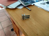
I finally cut some parts just now, these are the first connecting rods of the parallelogram ready to glue up on the jig that carry the 10mm bearings, when they arrive.
Makes me admire even more all your craftsmanship! 10mm I.D. tube sliced off and 4mm square tubes. Should be 3 grams each with the bearings.
Attachments

My reaction to these kind of bearings , as well as the Schroeder tonearm, is that there seams not to be a very good mechanical grounding through these bearings . I like as rigid a connection as possible from cartridge body to mechanical ground. I could be very wrong, though.
+1
I finally cut some parts just now, these are the first connecting rods of the parallelogram ready to glue up on the jig that carry the 10mm bearings, when they arrive.
Makes me admire even more all your craftsmanship! 10mm I.D. tube sliced off and 4mm square tubes. Should be 3 grams each with the bearings.
Nice Mike!
I am almost on the same route as you Mike, but maybe it is the wrong road considering the thoughts in #2695 ?.
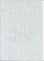
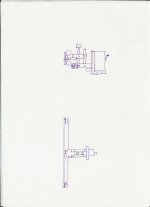
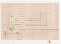
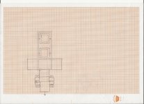
My take on this is two 6 mm carbon rods. The bearings are from some turning coil instruments I had lying around. The pinol screws have a spring loaded seat inside and I made some 1 mm pins from 1 mm drill shafts machined with a point shape that goes through the carbon tubes and into the seats.
Weights less than 5 gr.
I am absolutely not sure , that I have made this with the precision required, but having fun trying...
Dimensions in second pic.
It could be used under the rail, in a passive arm as the third pic, or over the rail as in the two last pics.
In the last example, the supporting structure would be an arm that moved , if the cartridge moved in the short rail.
The last two sketches were made before I actually made the parallelogram, so the dimensions are off.
Attachments
Niffy...
I know that this suggestion is somehow contradicting what I said about rigidity, but compromises has to be taken somewhere 😉😛
I know that this suggestion is somehow contradicting what I said about rigidity, but compromises has to be taken somewhere 😉😛
My reaction to these kind of bearings, as well as the Schroeder tonearm, is that there seams not to be a very good mechanical grounding through these bearings. I like as rigid a connection as possible from cartridge body to mechanical ground.
I also like as rigid a connection as possible.
Admittedly in the context of cartridge suspensions, I have tested pin bearings, tensioned metal wire, and other methods, and preferred the tensioned metal wire, which gives excellent mechanical grounding along with lower noise.
Note that this is how the vast majority of MC phono cartridges are made - with tensioned wire suspensions. However, there have been a few with rolling or moving contact suspensions - such as some of the Glanz designs.
- Home
- Source & Line
- Analogue Source
- DIY linear tonearm