Hi Carlo,
I wondered about this too, most minor warps are taken up with the play in the bearing. This warp is much bigger and tilts the wheel on the rail. My wheels have a very small radius. I wonder if increasing the radius would reduce damping?
The clamp solved this problem and will flatten almost all warps except one I have where the LP has a bump, this is one of my torture test LP and I have yet to find any combination that will track it.
I still have on my todo list to build a new carriage with pin bearings.
Seeing that behavior of the cantilever reminds me that of the first Lil Casey (MK1 #2501), that led me to completely revise the arm, by minimizing vertical masses and parallelogram's friction (MK2 carbon #2906). While there is a real advantage for carriage movement, achievable even by unsophisticated means, the vertical masses and parallelogram bearings friction are the real problem to overcome for a radial-rail tonearm.
So, seeing similar issues in a rather conventional LTA is frankly surprising, although confirming my prejudices on the non separate - Cantus like - vertical articulations (#3141)
Since i'm used to evaluate my arms with my eyes much more then with ears, my "crash test" is set up far bejond RIIA specs: -- eccentricity + - 1,5 mm - warp 3 mm; the AT95 cartridge is certainly stiffer than the Stanton 881, but cannot be defined a low comp for sure.
carlo
beautiful clamp, may you post a drawing?
Hi Carlo,
I don't have a drawing, I'll have to do one.
The clamp is made from 10mm thick Delrin and is 88mm in diameter. The recess on the bottom is 2mm deep with the lip about 3mm wide. The taper on the top was machined to miss the carriage and rail.
The collet thread is M10 1.5 and the taper is 16deg. The felt washer is 8mm thick and 25mm diameter.
The collet was the hardest part to machine because it's so short. I am going to make another clamp thicker at 20mm. I have ordered 300mm of 90mm OD Delrin to make another.
Thanks for the description which already explains how it works. Just as I have no difficulty to imagine the troubles in machining that taper, especially for the female holder.
For steep warps I don't know any remedy (except to throw away the LP). but for distortions a cardboard ring under the outer part of the disc works quite well (considering how long it takes to try it) - look at # 2817 # 2833
carlo
For steep warps I don't know any remedy (except to throw away the LP). but for distortions a cardboard ring under the outer part of the disc works quite well (considering how long it takes to try it) - look at # 2817 # 2833
carlo
The female taper was easier than the male, just set the compound to 16deg and I didn't move it until the tapers were finished.
I machined a 0.8mm dished platter which worked ok but didn't flatten cupped LP's this clamp & washer flattens both on a flat acrylic mat. My clamp was modeled on this one.
YouTube
I machined a 0.8mm dished platter which worked ok but didn't flatten cupped LP's this clamp & washer flattens both on a flat acrylic mat. My clamp was modeled on this one.
YouTube
the machinist corner - offtopic
what do you use to bore such small holes? I've ground some D shaped tools from drillbits, but it's not so practical to align the cutting edge with the proper angle, and still was unable to grind a tool to make small internal slots with the right precision.
EG - for my friction clamp, with two O rings inside, I had to glue a compound of several overlapping discs with a front slot
carlo
For the hole I drilled 17/64 (6.75mm) pilot and then used a boring bar I ground from an old 6.5mm drill, I'll take a photo of my boring setup on Saturday as I don't have lights in my shed. Because the boring bar is so thin I take a lot of light cuts as the bar will flex a lot.
To grind the boring bar I cut the drill leaving about 10mm of twist. With the bit in my cordless drill I thinned the drill just enough to give clearance in the 6.75mm hole and also leaving about 6mm of the end to grind the cutter. The cutting edge was ground on the end of the twist.
Process for my next collet will be
1 - Machine 10x30mm spigot and cut thread.
2 - Turn the entire bar around and hold the threaded end in a split collar in the chuck and the other end in a live centre.
3 - Machine the 16deg taper and cut/part off.
4 - Machine flat, drill hole 17/64 then bore to 7.2mm
5 - Cut slits in collet.
I thought I would post this here as well as in the Air bearing arm for reference for others.
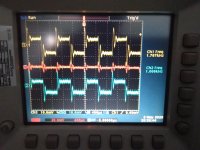
Here is a shot of my LTA, inspired by Niffy's design, tracking the CBS STR112 1kHz square wave.
NOTE: I have used no loading except the scope input 1MR and 33pf so the ringing is a bit high as my Stanton 881s needs 47kR and 275pf.
CH1 Left and CH2 Right red trace is math function CH1 - CH2, NO averaging
Attachments
?'s
Hi Warrjon,
Could you do another screen shot with the cartridge properly loaded ?
Does your fixed bearing still have a lot of horizontal movement as shown on the youtube video?
tia,
dennis h
Hi Warrjon,
Could you do another screen shot with the cartridge properly loaded ?
Does your fixed bearing still have a lot of horizontal movement as shown on the youtube video?
tia,
dennis h
Hi Dennis,
I can do another square wave measurement but I'll need to get a longer set of RCA leads. The RCA's from the TT to the preamp are very short to keep lead capacitance low.
The horizontal tracking is much better and the arm does not miss track unless I fiddle with the height. The carriage is running a bit tail up ATM to allow enough room for 180g LP's and clearance when cued up on warps. I need to add a thicker spacer under the cartridge.
I found getting the arm level can't be done with a level, I need to lower the stylus on the platter without an LP and watch for cantilever deflection, doing it this way improves tracking significantly.
Thanks , Warrjon
I had heard that tracking with short arms is a challenge.
Looking forward to your continued progress.
dennis h
I had heard that tracking with short arms is a challenge.
Looking forward to your continued progress.
dennis h
Hi Dennis,
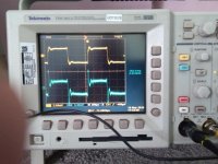
Here is a screen shot with one channel plugged into the phono-pre and the other directly into the scope. Yellow trace is phono-pre blue trace is the TT plugged directly into the scope. So capacitive loading is 330fp yellow and 33pf blue.
Here is a screen shot with one channel plugged into the phono-pre and the other directly into the scope. Yellow trace is phono-pre blue trace is the TT plugged directly into the scope. So capacitive loading is 330fp yellow and 33pf blue.
Attachments
This comparison is very interesting and really new for me, Warren; often we try to split the hair in 4 while forgetting all the rest, starting from the cartridge loading. For example very few of those I know measure the cable capacity, and take it into account, even if a wrong load changes the sound more than the worst tonearm.
Perhaps it would be interesting to do the same measurement on every step of the whole audio chain: 0 - at the cartridge output; 1 - at the pre phono input; 2 - at the pre phono output; 3 - at the amplifier input; 4 - at the amplifier output ; 5 - after the cross over; 6 - on the mid speaker terminals.
The ideal would be to generate the signal not from a track on the test disk (therefore from the sum of the imperfections of the recording and the support with the resonances of the turntable and the tonearm ) but by directly soliciting the stylus (with a piezo buzzer?) with the cartridge tied to an almost non resonant support.
This in order to be finally able to separate the crimes of our tonearm from those of all the rest of the gang
carlo
Last edited:
I did that using an LCR bridge.
Tonearm wiring 10pf
Cable from TT to phono pre 32pf
Phono pre 210pf
Total loading is a little low for my Stanton at 250pf total.
My interconnect is very short 300mm and DIY made from 2 core shielded microphone cable.One core is + the other is - and the shield is only connected to - at the phono-pre end.
The scope photo above I was playing with capacitive loading on the phono-pre to get the best balance.
If you look at the difference between the 2 channels you can see 2 things.
1 The leading/training edges on CH2 (blue trace) are more vertical than CH1 (yellow trace) this indicates higher frequency response of CH2. CH1 has too much capacitative loading at 360pf including 33pf of scope.
2 The ringing on the leading/trailing edge of CH2. This oscillation will have the affect of making the sound very bright.
.
Hi Warrjon,
The trace through the phono looks like the trace bypass the phono. At least, both look like square waves. But what I didn't understand was, in my tests, it looked like a triangle wave through a phono. My cartridge was an MC, so the output must be lower than yours.
Jim
The trace through the phono looks like the trace bypass the phono. At least, both look like square waves. But what I didn't understand was, in my tests, it looked like a triangle wave through a phono. My cartridge was an MC, so the output must be lower than yours.
Jim
Warrjon,
Thanks for the square wave shots in post #3652
And the additional loading info in post #3654
Keep up the good work
I for one appreciate the training and your hard work
dennis h
Thanks for the square wave shots in post #3652
And the additional loading info in post #3654
Keep up the good work
I for one appreciate the training and your hard work
dennis h
Hi Jim,
Sorry I wasn't clear. The scope shot in #3652 was the input to the phono-pre not the output. If I was to scope the output it would be a sawtooth (triangle) wave.
Scoping the input with this LP gives an indication of how well loaded the cartridge is and in both the cartridge is not correctly loaded CH1 is too much C and CH2 is too little C.
Straight rails
Warrjon,
Thanks again for that tip about the granite plate and the Vee Blocks. I was not so lucky with HSS rods, but the Carbide rods from Castlebar (on ebay) were pretty good.
I had to cut mine down from 13" with a Dremel like diamond wheel. That turns out to be a poor idea because there's a WARNING sticker - CANCER. There's Cobalt in the mix and it's a suspected Carcinogen. Better to buy the right length. I wonder how many ebay sellers don't bother with that warning.
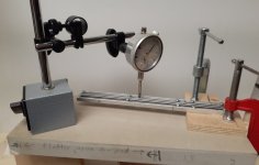
The Dial Indicator worked out very well for tweaking the rods to straighten them. I measured each rail at 1" increments and plotted the results...
I have a 24'" granite surface plate. Place rods on Vee blocks and run a test indicator over them. Rotate the rod and check again, I used the Vee block clamps on top of the rod to hold it.
Also just rolling the rods on the surface plate you can hear the uneven roll if they are bent, even a small amount. The worst ones rocked back and forth.
Do it multiple times to ensure repeatability.
Warrjon,
Thanks again for that tip about the granite plate and the Vee Blocks. I was not so lucky with HSS rods, but the Carbide rods from Castlebar (on ebay) were pretty good.
I had to cut mine down from 13" with a Dremel like diamond wheel. That turns out to be a poor idea because there's a WARNING sticker - CANCER. There's Cobalt in the mix and it's a suspected Carcinogen. Better to buy the right length. I wonder how many ebay sellers don't bother with that warning.
The Dial Indicator worked out very well for tweaking the rods to straighten them. I measured each rail at 1" increments and plotted the results...
Attachments
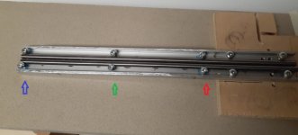
There's a 0.025" spacer under the bolts highlighted with the red and blue arrows. Those bolts are snugged up to trap the rods. Then the bolts by the green arrow are tighten in stages to flatten out the rod. The dial Indicator measures the results.
Applied hot glue from under neath to fill in the gaps and keep everything in place.
I used something similar to Carlo's friction test to see the results. Flattening the rods gave me much more uniform results. Very happy with how it turned out.
Hugh
Applied hot glue from under neath to fill in the gaps and keep everything in place.
I used something similar to Carlo's friction test to see the results. Flattening the rods gave me much more uniform results. Very happy with how it turned out.
Hugh
Attachments
I had to cut mine down from 13" with a Dremel like diamond wheel. That turns out to be a poor idea because there's a WARNING sticker - CANCER. There's Cobalt in the mix and it's a suspected Carcinogen. Better to buy the right length. I wonder how many ebay sellers don't bother with that warning.
I also cut my carbide rods with a diamond cutter in a dremel. I did mine under a constant flow of water, although I did this in order to cool and lubricate the cutter. Looks like my method would have had an additional benefit in suppressing dust.
Thanks for the heads up.
Niffy
- Home
- Source & Line
- Analogue Source
- DIY linear tonearm