Really surprised that a conceptually simple and self-aligning carriage, so beautifully made by Warren, could face unexpected problems, i've tried to examine the possible faults sources in a so small V bearing.
Here some sketches on these thoughts.
carlo
Here some sketches on these thoughts.
carlo
Attachments

Hi Carlo,
I made the Vee's 90deg and the pins 60deg so any slight miss alignment didn't cause binding.
OK I'll fess up when I drilled the M3 holes in the carriage for the Vee set screws the drill wandered in the polycarbonate, I had the speed slow so the PC did not melt, but small drills 2.5mm like faster speeds to stay straight. My next carriage I am going to use aluminium for the Vee screws.
When I measured the wheels the RH wheel was slightly tilted so the carriage was fighting this. With the Boca bearings this does not matter as there is enough slop in the bearing to align it correctly.
I'm listing to LP's now and I'm really happy with what I hear. I have had the privilege to listen to a few very high end systems and I must say this is as good as I have ever heard.
Hi Warren. doing those drawings I realized that there are more problems around than the simplicity of the V bearing suggests. With such small dimensions the tolerances become really difficult to maintain (impossible for me), and a few extra milligrams of friction are enough to bring a lot of trouble.
he thing that surprised me more is the slanting of the wheel (and there are 2, unfortunately) caused by the tilting of the cups. The pivot has to find a circle section on the cone, tilting it's own axis.
I am watching the cantilever in your video, which seems very good with such a big eccentricity. What I can't understand is the brush behavior - It is certainly better (the brush does half the work) but also strange, it seems like being late with respect to the carriage.
Is the channel difference track coming from a mono master?
ciao carlo
Hi Carlo,
Yes tolerances in such small components are hard to get perfect , especially for old eyes. I re-checked the wheels to ensure the pins were centered and they are good. The problem was the Vee was not centered in the mount so it made the wheel tilt outwards.
The Stanton/Pickering 881/XSV3000 are very high compliance (30Um/nM 50% higher than the 2M black) and needed a tonearm with very low mass. The brush assisted with these cartridges tracking in medium mass arms. In my Technics EPA100 there is almost no resonance).
The channel difference is from the Ultimate Analog test LP track 1, 1kHz lateral mono, I was using it to check azimuth, which seems pretty good.
I knew when I started this getting the Stanton to track would be a challenge. But once you have heard a Stanton 881 / Pickering XSV3000 sing, there are not many cartridges out there that will better it at any price. The Stanton 881 was hand picked and tested to meet specification., ruler flat frequency response 35dB separation and better than 1dB channel balance. I did a sweep 1kHz to 10Hz today and the Stanton was less than 1dB down at 20Hz
Would you consider that the torque around the carriage centre might make the pivots climb in the cups? I seem to recall only the bottom being polished.
Also, Niffy has laid the groundwork here and the application calls for super hard materials to function correctly, ceramics and crystalline are the way to go but I do understand the supply problems as I have the same in my own projects.
Although the weight is very low here, the 4 contact points in the cups are very tiny, you could perhaps calculate the force at the points and determine if the materials are adequate. If the coefficient of friction and the force at these points overcome the slip in the cups, the pivots could run like a roller coaster in the bottom of the cups for oscillating torque.
There might be some evidence of this in the video without the brush, not 100% sure though.
You have done all the hard work already and to reach the same results as Niffy is not far now. Well done.
some more thoughts on V bearings
A - springed V jewel = elastic system, zero clearance needed
A1; maybe + friction 0 chattering -- A2; if slanted the V cup induce a pivot tilting to find a circular contact
B - V jewel + tuning screw = rigid system, some clearance needed
B1 maybe - friction + chattering -- B2; even with a slanted V cup, the pivot can stay aligned.
In B case the carriage weight determines friction and chattering - an heavier one seems beneficial against chattering, and, strangely, also some jewel misalignment (more stable contact)
carlo
just an hypothesis of course, but somehow confirming Niffy's reports about clearance and better sounding heavier carriages
Attachments

Hi Carlo,
For our application I believe that the rigid system (B) is preferable. As the bearing is under constant load with a high contact pressure there will be no chatter. The friction will tend to be lower if there is a small amount of end shake, 5-10um. The sprung vee mounts are designed primarily for shock absorption for use where there is strong vibration or shock such as portable meters that run the risk of being dropped. The sprung mount is designed to prevent the jewel from being damaged. It is not designed to help align the bearing. As the pivot contacts the spherical cup of the vee and not the conical section absolute alignment is not critical.
Niffy
Hi Warrjon,
When I was using my homemade bearings the measured friction was about 1.4 times that of the jeweled bearings (but still less than half of that when using ballrace bearings). From your photos it looks like you made your bearings at least as well as I made mine. Combined with your cartridge having a compliance almost half as much again as mine I would expect the deflection of the cantilever to be about double what I observe with my arm.
That you are getting lower friction with the ballrace bearings definitely points to a problem with the pin bearings. I never suffered any skipping with the ballrace bearings and the pin bearings had much lower friction again.
Good luck and stay safe.
Niffy
yes, after those drawings I am convinced too that B is much better, especially with a carriage of a certain weight; otherwise the rotation could cause the pivot to climb on the Vee surface, with some irregular motion.
After all, V bearings are usually used vertically.
carlo
horrible events all around us
After all, V bearings are usually used vertically.
carlo
horrible events all around us
Hi Niffy,
I have no miss tracking with the ballrace bearings, except the occasional caused by the wiring, it took a while to get the wiring in the correct place. As my arm moves backwards and forwards to change records this sometimes moves the wiring.
As the ballrace wheels are 2.5mm wide they obviously sit higher on the rail so can disengage from the rail much easier, the 2 neodymium magnets each side I used to hold the arm forward are too strong and it almost always bounces the carriage off the rail.
You mentioned you use a periphery weight I have looked around and the only ones I can find are around $700AUD, what did you use?
I did find a problem with the pin bearing Vee mount and I am going to make a new carriage so I can use pin bearings.
Last edited:
Hi Warrjon,
I use a screw down reflex clamp that is very effective at flattening warps. Jim uses a peripheral clamp.
I don't think that a peripheral clamp needs to be very heavy in order to get rid of even severe warps. Half a kilo total weight would probably do it, though I would recommend testing first. Commercial peripheral clamps are too heavy in my opinion. The manufacturers claiming that the increased inertia aids speed stability. What tends to happen is the high mass overloads the bearing causing more speed issues than the inertia cures. Balancing and Centring of heavier clamps is also more critical. With a deck like yours speed stability isn't going to be an issue. If I was going to DIY a clamp I would probably make it out to acrylic so that it will be impedance matched to the record and my platter.
Niffy
Hi Warrjon,
Balancing and Centring of heavier clamps is also more critical. With a deck like yours speed stability isn't going to be an issue. If I was going to DIY a clamp I would probably make it out to acrylic so that it will be impedance matched to the record and my platter.
Niffy
Yes the SP10 speed stability is about as good as it gets. Some have modified the SP10Mk2 platter to increase weight by 1kg with a copper mat with no issue to the bearing.
I don't have a lot of warped LP's worst is Stevie Wonder, I had to raise the rail as the LP was hitting the rear of the carriage. I do have a 400g centre weight which made the situation worse on this LP.
I never thought of acrylic that's a good idea. I was going to make it from aluminium, but I have some acrylic that might be big enough
Hi Warrjon,
Most types of central clamp have a tendency to make warps worse. The force exerted by the clamp pushes the centre of the record into the label cutout in the platter which causes the edges of the record to rise up. A reflex clamp has a raised area around the spindle. The clamp pushes down around this causing the edge of the record to be forced down onto the platter. This both flattens warps and forces the record into a more intimate contact with the platter. Even records that look pretty flat are improved by this system. My reflex clamp is so efficient that I have to pry up the edge of the record with a thumb nail to let some air in before I can remove it from the platter. This video was originally posted to show lateral tracking but so shows how little the cartridge moves up and down due to warps.
YouTube
A peripheral clamp will definitely help with the more severely warped records or in situations where a reflex clamp can't be implemented. One important factor with a peripheral clamp is the thicknesses of the lip that holds the record down. With my arm, that only raises the stylus a couple of mm above the record when queuing, the lip would have to be very thin. I do have some 0.2mm carbon fibre that would probably be ideal.
When using arms as short as we are using a good clamp is essential. I consider the clamp to be more a part of the tonearm than it is the deck. At first glance you might expect the clamp to have the greatest impact on reducing VTA errors due to the reduction in movement about the vertical pivot. The reduction in VTA errors in actually mainly due to the reduced surface angle of the record. The effect of a good clamp on VTA is much greater than first appearances would suggest.
With a short arm with a raised pivot point the main cause for concern is warp wow. Flattening the warps has a noticeable effect on the timing of the music. Everything sounds more solid and precise.
Don't give up on the pin bearings. With home made bearings and your cartridge you should be able to get the stylus displacement down to about double that seen in this video. It took me many iterations before I got there.
Niffy
Hi Niffy,
You are correct the centre weight made the LP curve up at the perimeter. I was thinking ( a dangerous pastime I know) if I made an acrylic mat with a small dish like the in the link. The rubber mat on the SP10 has the label indent (which I think is too deep) but the mat is flat.
[DIY] TNT DIY Acrylic Turntable Mat
I have been thinking about the periphery clamp but I have not yet devised a way to machine it in the lathe, my lathe will hold 330mm but I would have to remove the gap and I don't want to do that too hard to get it back in. The commercial clamps are milled but I don't have a rotary table.
I have not given up on the pin bearings I am planning a new carriage that will use pin bearings. The mistake I made with the current one was two fold. I drilled the polycarbonate for the M3 Vees too slow and I suspect the drill wandered. I also drilled after shaping the carriage top so I had to line it up to drill with a square. It was not out by much visually it looked ok but if you put a straight edge (100mm carbide rod) between the wheels it was obvious.
This time I will machine the top of the carriage rectangular so I have the bottom perpendicular to the sides this way I can get the screws in the correct location. I'm a electronic Tech/Engineer by trade not a machinist so still learning the finer details of the art.
The RH wheel was pointing ever so slightly outwards so as the carriage moved it was trying to twist add that to the slight out of round of the carbide ring and I think these 2 things added up to miss tracking.
Hi Warrjon,
As a simple experiment you could try some different thickness penny washers over the spindle. One that is slightly thicker than the depth of the label recess would be a good starting point.
Depending on the material you want to make a peripheral clamp from you could just use a router with a circle jig. I made my platter using a router and that came out very well.
When fitting the mounting blocks, for the bearings, to the carriage I made a jig to ensure that the axles were aligned and parallel. My vee bearings were made from M3 screws. After making the mounting blocks I threaded a long length of treaded bar through both so that they were held the correct distance apart. The ends of the threaded bars were fitted into spacing blocks that made sure that the bars were parallel. Marks on these blocks also allowed me to make sure that the bars were parallel to the axis of the carriage. Whilst the adhesive, that hold the blocks in place, was curing the whole thing was clamped to a flat surface to ensure that the bars could not twist and to make sure that azimuth was correctly set.
If I was to make the carriage again I might be tempted to make the mounting blocks from aluminium rather than acrylic. Although these would be heavier they should offer slightly better coupling of the carriage to the rail. I doubt the difference would be significant.
Niffy
Hi Niffy,
My Vee's are high tensile M3 grub screws. I machined the carriage in the milling machine, which has a Digital Readout with 0.005mm precision. So I can centre the chuck and drill holes at Xmm each side of centre in X and Y axis. I used polycarbonate for the mounting blocks which did not drill well at low speed. I am going to use aluminium for the next mounting blocks.
Last time I drilled the holes all the way through from one side so the drill must have wandered. Next time I am going to drill/tap each Vee mounting hole separately.
I measured the black acrylic I have and it's 3mm thick and just over 300mm square so I might use this for a mat. I have some 10mm thick polycarbonate that is big enough to make a peripheral ring from..........I have a router circle jig - good thought
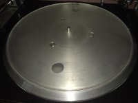
I found some 5mm clear acrylic so made this. It's the same outside thickness as the SP10 mat. I cracked it trying to machine the last little bit near the spindle.
9 steps of 0.08mm with label indent 0.1mm below the 9th step. Unfortunately it didn't flatten the 180g LP as I had hoped, but the sound was better background noise dropped and detail improved. It was a success but not in the way I had expected. I will need to make a periphery clamp.
9 steps of 0.08mm with label indent 0.1mm below the 9th step. Unfortunately it didn't flatten the 180g LP as I had hoped, but the sound was better background noise dropped and detail improved. It was a success but not in the way I had expected. I will need to make a periphery clamp.
Attachments
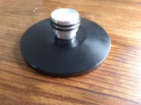
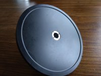
Dealing with bad warps. I had hoped that the dished mat would work but alas it still didn't flatten dished LP's and I don't have room to use a periphery weight. So after some research I decided to make a clamp and felt washer similar to the Mitchell.
I made a new mat this time flat with a 0.75mm label recess.
Here is a short video the first is with a weight the latter is with the clamp installed.
YouTube
I made a new mat this time flat with a 0.75mm label recess.
Here is a short video the first is with a weight the latter is with the clamp installed.
YouTube
Attachments
Hi Warren.
Warps are warps, unfortunately; but this video, showing an apparent vertical bending of the cantilever before the carriage tilting seems difficult to understand.
Since the vertical effective mass of such a short and lightweight arm should be really small, this leads to suspect a problem of excessive friction in the vertical articulation. Too much damping from the rounded section wheels while tilting on the V rail, or what ?
carlo
- Home
- Source & Line
- Analogue Source
- DIY linear tonearm