Hi Niffy, it's a simple test, very diy style, hope that others will do the same on different cartridges.
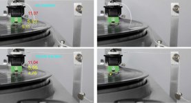
Here the measures by the other side. (attachment) The sum left + right is 10.24 and 10.31 then a stylus of 0.7 mm ca (plausible) - on the right picture the bending is clearly evidenced; you may note that even without traction the stylus is not perfectly at 0° (the camera was aligned to the shaft-cartridge): do you remember my thoughts about cartridge tolerances?
Of course a rough experiment like this, done on a single cartridge does not prove anything. There are also ample margins of error in the measurements: what I could do was to scale the picture on the base of cartridge size (about 11 mm ca, all casted plastic have a taper) and use a program thatgives dimensions automatically, repeating the measurements on different photos.
However the behavior is near to what seen with a macro-scope for years, and to everyone's experiences: when an arm tends to skipping on eccentricities we may see with naked eye the stylus visibly oscillating and this, as you rightly noted, corresponds to movements well above 0, 2 mm.
1 gr is more than twice what generates skipping on a modern cartridge, so much that the VTF had to be more than doubled to do the test. This unusable VTF limits stylus movement considerably.
Now I do not think at all that the compliance indicated by the manufacturers (for the calculation of the resonance of the cartridge-arm system) is wrong, on the contrary I have only the doubt that it can be directly used not for micro-movements during tracking, but for movements caused by the side force, much bigger.
carlo
tests bring doubts...
Attachments
Hi Niffy
In your post 2061, 24/6/16 you state
“Calculating the horizontal effective mass of a linear tracking arm is easy, it's just the mass of the arm.”
Still ok? This I can deal with 😀
Thx
Coolerooney
Still OK........ IF you have a good stiff bearing with very little play.
If you push the carriage sideways at the stylus it doesn't naturally want to move its entire mass in a linear fashion but does so as it is constrained by the bearing. It would much rather rotate about its centre of mass as this requires the lowest amount of energy. At low frequencies and large amplitudes (like when tracking an eccentricity) the carriage will move in a linear fashion. As you increase in frequency, into the audio range, any bearing play will start to allow the carriage to rotate about its centre of mass. The greater the play the lower the frequency that this will become significant. As all bearings have a certain amount of play this will inevitably happen with all arms. With a very stiff bearing like a high pressure air bearing this will probably be high in the audio band. With ball race bearings this will probably become significant below 20hz. How to determine how this will effect any particular arm is not obvious.
Once the carriage is rotating about its centre of mass its effective mass will no longer be its entire mass. It will be that calculated as for a conventional pivoted arm with the lateral pivot point taken at the centre of mass.
So as frequency increases effective mass will decrease.
For the purpose of determining the resonant frequency of the cartridge suspension it is safe to assume that the entire mass is the effective mass.
Niffy
Niffy,
Thank you for your continued educational effort, it is greatly appreciated.
Think I got it ( a bit- ha) (but the pics above of nocdplz freak me out)
I am CAD-ding up my arm, will be zero length, i.e. Center of the rotational shaft is in line with the stylus- like nocdplz’ Lil Casey, but rotation freedom is preserved
Linear Bearing friction is non issue- thx for that!-Active control, movement of TA by stepper motor and threaded shaft, magnetically decoupled
Radial bearing-good, but not OTT- put in a lot of effort to avoid effect of warped discs
😀
Coolerooney
Last edited:
Niffy,
Thank you for your continued educational effort, it is greatly appreciated.
Think I got it ( a bit- ha) (but the pics above of nocdplz freak me out)
I am CAD-ding up my arm, will be zero length, i.e. Center of the rotational shaft is in line with the stylus- like nocdplz’ Lil Casey, but rotation freedom is preserved
Linear Bearing friction is non issue- thx for that!-Active control, movement of TA by stepper motor and threaded shaft, magnetically decoupled
Radial bearing-good, but not OTT- put in a lot of effort to avoid effect of warped discs
😀
Coolerooney
It sounds like a very interesting project
Hi Carlo,
If I didn't have 3 audio projects and a couple of boring domestic ones on the go at the moment I would be digging out my bearing test rig, repurposing it, and trying your experiment myself. I think it might be easier to get meaningful results by not just trying to look at cantilever deflection relative to the cartridge body but just how far the cartridge body moves. Maybe, rather than using a record, use a plate with a pit the stylus sits in. This will ensure that the stylus is always in the same place. When you apply the traction the cartridge body will move relative to the fixed stylus. If a pin or some type of marker is attached to the top of the headshell and a fixed scale is attached just behind it relative movement can be directly read without having to even look at the cartridge itself. Maybe a micrometer could be used to measure the difference in no traction and traction.
Ni Coolerooney,
An interesting project indeed. Please post pictures and discription as you get bits built.
Niffy
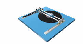
Just a quick pic the entire assembly moves backwards for record change - motorized with a Core XY layout- not shown - like an Etch a Sketch
The four blocks on the right (Pic 2) are the carriage- 2 straddle the nut that is connected to the threaded spindle 1 block carries the cartridge and is the only one that can rotate (a bit) the other one behind it carries the stepper for the needle up/down
The 2 right most bearing blocks are not physically connected to the cartridge bearing block, it gets pushed
The stepper will take about 20,5 million steps for a 10 cm, 200gpi record track (17k steps/sec)
Each step will move the cartridge 0,0000048 mm
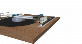
I use standard Igus parts where I can, for speed of construction, but also for size stability- with these tight tolerances it is easy to screw it up
Shafts are 10 mm dia tubes, carry wires
Other cabling is managed by "energy chains" the little plastic ladders
By minimizing record warping, the requirements on the radial bearing and the cartridge compliance are reduced- alleviating this TA design issue
I am taking some cues of the AVDesignhaus Dereneville, a 40k arm, but on a shoestring budget, nevertheless there are some areas of improvement
Coolerooney
The four blocks on the right (Pic 2) are the carriage- 2 straddle the nut that is connected to the threaded spindle 1 block carries the cartridge and is the only one that can rotate (a bit) the other one behind it carries the stepper for the needle up/down
The 2 right most bearing blocks are not physically connected to the cartridge bearing block, it gets pushed
The stepper will take about 20,5 million steps for a 10 cm, 200gpi record track (17k steps/sec)
Each step will move the cartridge 0,0000048 mm
I use standard Igus parts where I can, for speed of construction, but also for size stability- with these tight tolerances it is easy to screw it up
Shafts are 10 mm dia tubes, carry wires
Other cabling is managed by "energy chains" the little plastic ladders
By minimizing record warping, the requirements on the radial bearing and the cartridge compliance are reduced- alleviating this TA design issue
I am taking some cues of the AVDesignhaus Dereneville, a 40k arm, but on a shoestring budget, nevertheless there are some areas of improvement
Coolerooney
Attachments
Last edited:
Hi Niffy, glad that this naive test has interested you.
one point: the measured movement is that of the cartridge body, the stylus remains fixed into the groove. therefore the edge of the cartridge can be a good reference.
The problem is all in the photo: the alignment is simple, just with a thread that goes from the base of the arm, through the cartridge to the center of the lens, and a spirit level for the vertical. But imagine one who worked for 40 years (as advertising photographer) with a Sinar view 8"x10" now doing such things with a pocket digicamera and a table lamp!
If I'll put my hands again on the test must be with the right VTF, and then with realistic SF: so with a pendulum, because the pulley has too much friction even with 500 mgr (proven). The idea of an "artificial" groove is very good.
Now I have called an old friend to try to calculate how much torque exerts an arm of length L on a cart L / 2, relating to the friction on the rail.
My neanderthal starting point is this: with maximum friction everything is torque = 0 advancement - with zero friction no torque = all advancement. The question is - what happens in the middle ?: that is, in our real world.
Nice model, Coolerooney; just one doubt: how will you manage vertical movements? It's the main problem of a radial rail
If only you could do without a servo, sometimes here those weapons are considered unfair ...
carlo
Hi Carlo,
First: nice work on Lil Casey, also the artwork!
The block that carries the cartridge can rotate- but off course more limited than a longer arm- Trying to manage the warp-which induces the height differentials instead-seeing the arm and record as 1 system
In theory (I know) if the record is 100% flat, the need for a radial bearing long or short arm would not exist
reduce warp- like with a ring, which are widely available, just don’t understand the pricing madness- Clearaudio’s is about 1k
Eccentricity is next- if it possible to “pre-process” the record to zero ecc (I know, I know) then it would be possible to work with a 1 sided weight to compensate for the groove push of the stylus. Also the stylus would be less stressed, and music more neutral
For the stepper set up it the most important is sensor resolution that controls it-microswitches won’t cut it- something more like the Goldmund T5
Also with ecc under control, the arm moves in only 1 direction making control a lot easier-
Stepper/servo- fight with everything there is- a Heretic is what I am (and is actually on the nameplate of the plinth)😀
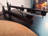
On the pic- found this on a Kickstarter project, interesting way of dealing with height variances independent of the arm
Have fun!
Coolerooney
First: nice work on Lil Casey, also the artwork!
The block that carries the cartridge can rotate- but off course more limited than a longer arm- Trying to manage the warp-which induces the height differentials instead-seeing the arm and record as 1 system
In theory (I know) if the record is 100% flat, the need for a radial bearing long or short arm would not exist
reduce warp- like with a ring, which are widely available, just don’t understand the pricing madness- Clearaudio’s is about 1k
Eccentricity is next- if it possible to “pre-process” the record to zero ecc (I know, I know) then it would be possible to work with a 1 sided weight to compensate for the groove push of the stylus. Also the stylus would be less stressed, and music more neutral
For the stepper set up it the most important is sensor resolution that controls it-microswitches won’t cut it- something more like the Goldmund T5
Also with ecc under control, the arm moves in only 1 direction making control a lot easier-
Stepper/servo- fight with everything there is- a Heretic is what I am (and is actually on the nameplate of the plinth)😀
On the pic- found this on a Kickstarter project, interesting way of dealing with height variances independent of the arm
Have fun!
Coolerooney
Attachments
Last edited:
Hello Coolerooney,
Is the step rate of the motor controlled by a servo?
Are you applying the principle of "base pitch" to the rotation of the stepping motor.
Sincerely,
Ralf
Is the step rate of the motor controlled by a servo?
Are you applying the principle of "base pitch" to the rotation of the stepping motor.
Sincerely,
Ralf
Hello Coolerooney,
Is the step rate of the motor controlled by a servo?
Are you applying the principle of "base pitch" to the rotation of the stepping motor.
Sincerely,
Ralf
Hi Ralf,
With “servo” you mean, I think, (hope) the stepper driver.
I use the TMC 5130 SilentStepStick driver, 1/256 microstepper via SPI interface to the MCU - the same driver is also used by the 40k Dereneville arm- a 17 euro piece at Farnell- setting up the parameters of the driver is more of a dark art 😉
The TMC’s cut noise and vibration dramatically compared to the 4988/8825 usuals-really amazing
Possibly use the TMC 2130 instead- 3-4 euro on Aliexpress- has less movement ramping options, but can get that elsewhere. The motor is a NEMA 8 or 11 size 0,9 degree stepper, i.e. 400 base steps/rev.
The Dereneville arm uses a 0,45 degree stepper, but has a coarser spindle
If understood correctly, base pitch will be effectively done, with theoretically 17k step/sec- the limiting factor is the sensitivity of the “off angle” sensor. ( the Deren arm is 5 microns, but laser costs 1200-not on Aliexpress hahaha). The gpi will determine the travel of the carriage in time-so to avoid start - stop mode a continuous move is possible, but tricky as gpi can be very different
Hope I understood correctly, otherwise teach me!

Thx
Coolerooney
Last edited:
Hi Ralf,
You triggered me
So instead of moving the motor after signal of deviation, move the motor continuously until the signal of deviation is received, then stop motor—same dev, just the other side of the arm- need to think on how to adjust speed relative to gpi
You triggered me
So instead of moving the motor after signal of deviation, move the motor continuously until the signal of deviation is received, then stop motor—same dev, just the other side of the arm- need to think on how to adjust speed relative to gpi
Hi Coolerooney, LP issues can be limited with proper storage (much easier and cheaper than all the devilries such as vacuum pumps, self-centering spindles, bearing-breaking weights) but can not be eliminated, because they will always be much wider than a groove pitch. So we have to accept and manage them with skill and simplicity (surely you know Herr Altmann ...), that's the game.
Back to us: if your " block that carries the cartridge" can tilt, it is not travelling on a radial rail; maybe something close to the Revox arm, deceased long ago: not leaving many regrets.
But excuse me: if you use a servo to overcome the friction of the carriage what's the need of a radial rail, or an ultra-short arm? It's the servo, not the arm that pushes the carriage.
Radial rail overcomes just one problem of linears (the torque on the carriage) introducing others of difficult solution: it is only an experiment, a constructive challenge to bring forward.
carlo
Hi Carlo,
On eccentricity: the Nak 1000 had a 0,1 mm spec (or so I’m told)
The main thing is to get within the compliance of the cantilever
The groove and land are about 0,127 mm(on a 200gpi disk)
Think I have it covered, but needs a bit more work
Agreed, the ultrashort arm is less/not necessary when active- just think it is elegant, compact
Not sure on the definition of “radial rail” my carriage runs over a round shaft, so that the cartridge carrying block can accomodate some height variances- as stated, need to keep these low, otherwise the concept fails
Following your drawings, your bearings runs inside the tube-right?
Best,
Coolerooney
Hi Carlo,
On eccentricity: the Nak 1000 had a 0,1 mm spec (or so I’m told)
The main thing is to get within the compliance of the cantilever
The groove and land are about 0,127 mm(on a 200gpi disk)
Think I have it covered, but needs a bit more work
Agreed, the ultrashort arm is less/not necessary when active- just think it is elegant, compact
Not sure on the definition of “radial rail” my carriage runs over a round shaft, so that the cartridge carrying block can accomodate some height variances- as stated, need to keep these low, otherwise the concept fails
Following your drawings, your bearings runs inside the tube-right?
Best,
Coolerooney
Love to see some pics in it
Not sure on the definition of “radial rail”
I've called “radial rail” a rail simply superimposed on a radius. (not so creative definition, Lil Casey was born to make a new (?) radial rail T.A. , not for the round section rail it uses). Linear trackers instead use chords, tangents or even lines outside the circumference for an easier disk changing.
Unfortunately my LPs are all under Riaa standards: eccentricity <1,27 mm. Never seen a similar disaster, never seen a perfectly centered disk
carlo
Last edited:
Hi Coolerooney,
Were you planning on using a mechanism for vertical articulation like that shown in #2629? To me this looks like really bad idea. This design has the cartridge mounted in the middle of what is basically a leaf spring. Resonance nightmare. Tracking force would also vary greatly with only a small change in record surface height. Even with a record that is flattened as much as possible with clamps/vacuum you will still have a small amount of "warp" due to slight variation in the thickness of the record. You also have to accommodate the overall thickness variation between different records, say between 150g and 180g pressings. Could you show a more detailed view of the vertical articulation mechanism?
What were you planning on using for the linear bearings? Although bearing friction is not an issue for a servo controlled arm bearing chatter is. Linear ball race bearings are not going to be ideal for this reason.
How are you isolating the stepped motor from the carriage? Motor noise can easily undo any advantages the servo may give.
Niffy
Last edited:
Fully agree with Niffy. Reading "kickstarter", often i can't avoid to think what kind of kick would be appropriate.
c
c
Ok guys,
No I am not going to use this, I thought it was nice try
See also
YouTube
On 2:00 you can see the vertical motion more clearly
On the vertical articulation required for varying thickness of records- I am playing with the concept of auto bed leveling used in 3d printing, which is a bit of a snag for me, as my platter is to be a “floater”, so move the arm instead, —hmmm-not there yet as it would require a subassembly, motors, drivers etc.
Pumping liquids is also possible, but not elegant
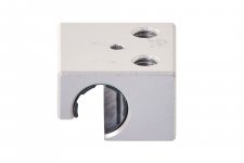
In the carriage the Igus bearing block is used, normally this is a part of a 4 bearing sleigh of the W linear rail system-with polymer dry bearing- see pic- the weight of the zinc alloy block is 17 grams, am using the aluminium-aluminum block 😀
In this design the blocks run on an Igus R type rail and end blocks, the whole arm assembly slides on N type rails
More: https://www.igus.com/drylin/profile-rail-guide
The cartridge will be attached to the block, which can also rotate. Small height differentials would compress the cantilever, bigger ones rotate the cartridge, (compromising VTA) but as mentioned before, intend to deal with this separately. A longer arm would make this less critical -I know
Stepper isolation
1-use SilentStepSticks- as described in previous posts
2- the cartridge carrying block is detached from the pushing blocks (which are connected to the spindle)-but still in contact- optional is a pull back of the pusher after each push, but there are too many pulses
3-magnetic coupling on the drive spindle (away from the cartridge)
4- optional- put the horse behind the carriage i.e. pull the cartridge block instead of pushing and use a silk thread between them as connection- when the carriage is returned to home position it is pushed. Think this one is better and more elegant
My 2 cents for the day, look forward to your remarks on my Noob-ness 😀 😀
Best,
Coolerooney
No I am not going to use this, I thought it was nice try
See also
YouTube
On 2:00 you can see the vertical motion more clearly
On the vertical articulation required for varying thickness of records- I am playing with the concept of auto bed leveling used in 3d printing, which is a bit of a snag for me, as my platter is to be a “floater”, so move the arm instead, —hmmm-not there yet as it would require a subassembly, motors, drivers etc.
Pumping liquids is also possible, but not elegant
In the carriage the Igus bearing block is used, normally this is a part of a 4 bearing sleigh of the W linear rail system-with polymer dry bearing- see pic- the weight of the zinc alloy block is 17 grams, am using the aluminium-aluminum block 😀
In this design the blocks run on an Igus R type rail and end blocks, the whole arm assembly slides on N type rails
More: https://www.igus.com/drylin/profile-rail-guide
The cartridge will be attached to the block, which can also rotate. Small height differentials would compress the cantilever, bigger ones rotate the cartridge, (compromising VTA) but as mentioned before, intend to deal with this separately. A longer arm would make this less critical -I know
Stepper isolation
1-use SilentStepSticks- as described in previous posts
2- the cartridge carrying block is detached from the pushing blocks (which are connected to the spindle)-but still in contact- optional is a pull back of the pusher after each push, but there are too many pulses
3-magnetic coupling on the drive spindle (away from the cartridge)
4- optional- put the horse behind the carriage i.e. pull the cartridge block instead of pushing and use a silk thread between them as connection- when the carriage is returned to home position it is pushed. Think this one is better and more elegant
My 2 cents for the day, look forward to your remarks on my Noob-ness 😀 😀
Best,
Coolerooney
Attachments
Last edited:
- Home
- Source & Line
- Analogue Source
- DIY linear tonearm