Groovvy
Hi all
As the record is cut, the position of the “stylus” cutter is determined by the cutting program that controls the linear speed. (Of the cutter arm)
I am assuming that the density of the grooves is uniform across the record (save for the spaces between songs) -any takers?
Thought experiment
The distance between the start and end groove is 100 mm- and is the lineair distance travelled by the stylus
If the playtime of the music is 10 min (one music piece), there are 333 rotations of the record
The nr of grooves are then is 333 and the groove size 0,3003003 mm (groove+land)
I call this the “groove map” a bit like a mountain range seen from the side
With this information the steppermotor speed for the TA can be set, without sensor information for/of the cartridge- and the record played- a bit like base pitch and servo integrated- Ralf- post2630/2641
Application-multi song
The number of music pieces and the spaces between the music are known, so is the duration of each music piece- the size of the spaces is unknown
By mapping the groove density across the complete record would allow to get the same situation as when the record is cut.- we know where the groove is relative to the stylus at any time😱
A few tricks can be used to reduce the difference vs the original “cutting map”
If only we could have the cutting map......
The mapping is conceivably done independent of the normal listening experience, and is different for each record
Problems: inconsistent manufacturing standards, spaces, accuracy of measurement, replicating the cutting linear motion-but for the rest, we’re fine😀
Look forward to your ideas
Greetz
Coolerooney
Last edited:
Hi Coolerooney,
I believe that most records are cut with a variable pitch. With analogue tape masters a second head reads the tape before the main head in order to determine the levels. Depending on the output from this second head the cutter slows or speeds up its rate of movement. This is to prevent one groove from breaking into or distorting the previous groove. This could be achieved by just having a wider groove spacing but this would limit the length of playback per side or would cause the record to be cut closer to the spindle where quality is lower. With digital masters the levels can be predetermined.
You could map the groove pitch for an entire side but you would have to account for even the slightest variation in platter rotation. This could be achieved by having an optical encoder on the platter and counting the exact number of revolutions. You would also have to make sure that you queue the record in exactly the same place, into the same groove each time. (I know that it is technically only one groove but you get my meaning) I think the typical groove spacing is closer to 100um.
You would probably need to account for the slight variation in the position of the record on the platter due to variation in the size of the central hole.
Niffy
Groove pitch - variable since Neumann lathe invention - 1950 ca. Sound engineers decide only average spacing due the length of music content to be cut on lacquer. Together with stereo and Riaa curve is what made Vinyl the great medium we love.
carlo
carlo
It has been puzzled me since I first played Philip Glass' soundtrack titled Powaqqatsi on vinyl, how the cutting people could manage to squeeze 68 minutes on it (Side A 33'27", side B 34'35"), and with great dynamics, good bass and all.
Let's assume you can map the groove for specific record for a specific table at particular moment perfectly. The driving mechanism can trace the map perfectly. Who wants to wait for completion of mapping before you play a record every time? I don't.
Let's assume you can map the groove for specific record for a specific table at particular moment perfectly. The driving mechanism can trace the map perfectly. Who wants to wait for completion of mapping before you play a record every time? I don't.
Hi Super
The idea is to store the map, and pull it up when you play the record- yes you will have to select the appropriate map prior to playing
Best
Coolerooney
Hi Super
The idea is to store the map, and pull it up when you play the record- yes you will have to select the appropriate map prior to playing
Best
Coolerooney
Problem is there is no single map to fit all records even on same table. Even for same record on same table, a single map is not good enough because center hole of record doesn't always fit spindle tightly.
Maybe there could be a "predict the future" system :
If we have a sensing device that travels ,say 2 groves, BEFORE the cartridge and tells a positioning system , where the pick-up should be , when it arrives to that position. Sort of a FIFO system with a delay. It could tell both horizontal and vertical position...
Could it be done?
And would it solve all the error correction of a normal servo arm?
Problem is there is no single map to fit all records even on same table. Even for same record on same table, a single map is not good enough because center hole of record doesn't always fit spindle tightly.
Hi Super- good point- working on that one btw- but difficult to get below 0,1mm, even then there a 1 groove width variance (about)
Maybe there could be a "predict the future" system :
If we have a sensing device that travels ,say 2 groves, BEFORE the cartridge and tells a positioning system , where the pick-up should be , when it arrives to that position. Sort of a FIFO system with a delay. It could tell both horizontal and vertical position...
Could it be done?
And would it solve all the error correction of a normal servo arm?
Hi koldby,
This one does a nice job
YouTube
The fiber is actually in the groove, the vertical responsiveness is something else!
The box of electronics is something else tooooooooo
Hi koldby,
This one does a nice job
YouTube
The fiber is actually in the groove, the vertical responsiveness is something else!
The box of electronics is something else tooooooooo
Exactly what inspired me to my suggestion.
We can arrange two wands like Beogram Linear Turntables. One would be used to find groove and with proper time adjustment control the motor to move the real tonearm across. Sorry noob posting here.I said it before. It seems to me that ELP tracking system is a better one. It tracks the groove before stylus( reading laser heads for ELP). However, I guess that the laser heads for reading groove may be ok if they are slightly high or low and right or left( I can be wrong here), but not for a regular cartridge.
regards
Maybe in 2020 a servo could implement in real time, in addition to the "mechanical" feedback, inputs coming from the musical content (higher volume or lows = bigger pitch - lower volume or highs = the opposite).
Since the linear trackers are always claimed to "track the way the cutting lathe did", this could start to be a little more true.
carlo
Since the linear trackers are always claimed to "track the way the cutting lathe did", this could start to be a little more true.
carlo
Hmmmm
So until we can “read the grooves” instead of tealeaves 😀😀
Have a second arm, with a “stylus of sorts” reading the “map” and feed forwarding this to the “music reading” TA
Have a great weekend all
Best
coolerooney
So until we can “read the grooves” instead of tealeaves 😀😀
Have a second arm, with a “stylus of sorts” reading the “map” and feed forwarding this to the “music reading” TA
Have a great weekend all
Best
coolerooney
Last edited:
Yes, ELP, as well as Laserdisc Player tracking system are very close to perfection (IMO). Together with real diamond stylus and hi quality MC or MM cartridge, instead of laser, and heavy platter of hi-end turntable, it is possible to combine advantages of both, and get a perfect LP playback deck. I would add there Nakamichi- like center search system, and some kind of LP flattener, integrated into the platter (vacuum? collet locking?) in order to approach audio nirvana...😀😀😀. And, of course, optically operated auto-stop should be there too. As well, as Capeheart style record changing device.I said it before. It seems to me that ELP tracking system is a better one. It tracks the groove before stylus( reading laser heads for ELP). However, I guess that the laser heads for reading groove may be ok if they are slightly high or low and right or left( I can be wrong here), but not for a regular cartridge.

Perhaps today to write some lines of code for Arduino, taking into account the signal output from the cartridge (frequency - volume level etc: several analyzing programs available around) to drive a servo, can be much simpler than to design, (and build!), strange micro lasers, double arms, and so on.
But I do not know almost nothing about servos. Maybe I' not alone.
carlo
But I do not know almost nothing about servos. Maybe I' not alone.
carlo
Hi all,
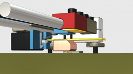
looking for advice- see attached pic
the red block can rotate and needs to be fixed to the cartridge- the yellow plates - there is about 10 mm between them- the stylus center is in line with the shaft center
the lower yellow plate is the "shell" for lack of a better word
considering glueing the upper yellow plate to the red block
the red block weighs 17 grams+the bolts, but can be made of plastic-don't like M6 holes staring at me, prefer the symmetry
the big green area is the platter
the black box is the stepper for the lift off
question: what is the best place to make the mechanical linkage and what place, shape
a bit of aluminium box, carbon fiber etc, foam
appreciate the help- don't be kind😛
coolerooney
Attachments
Last edited:
Sorry Coolerooney but I can't work out how the arm works at all from the picture. I assume that the red block is the lateral bearing. You say it can rotate, does this mean that it is involved in vertical articulation as well? How is vertical articulation actually achieved? How or is the lower yellow shell connected to the upper yellow piece / red block? Why does the yellow shell extend so far in front of the cartridge? What are all the blue bits? Are they to do with the sensor for the servo?
Maybe show some simpler plan and elevation diagrams of the principle rather than the finished item.
Sorry for so many questions but unless I fully understand the design I cannot honestly offer advice.
Niffy
Maybe show some simpler plan and elevation diagrams of the principle rather than the finished item.
Sorry for so many questions but unless I fully understand the design I cannot honestly offer advice.
Niffy
- Home
- Source & Line
- Analogue Source
- DIY linear tonearm