3 years ago I finished making a 'Floater' [Arm floats on water across an ice cream tub] & was so pleased with the results, all I wanted to do was listen to my vinyl.
You must be talking about something like this and this and this.
I've been thinking a lot about that design and it revised my idea about tangential tracking. I want to keep the same concept but I want to replace the water bowl with combination of rollers/linear bearings and pivots and, hopefully, still simple. The idea of having a water bowl close to my records makes me uncomfortable but that's why we look for alternatives!
Look forward to seeing your new creations!
@directdriver,
Don't waste your time. You better can look for another design of a tonerm. The quality of that tonearm depends on the floating unipivot (no resonances and "automatic" azimuth). Without the floating unipivot is is rubbish.
Don't waste your time. You better can look for another design of a tonerm. The quality of that tonearm depends on the floating unipivot (no resonances and "automatic" azimuth). Without the floating unipivot is is rubbish.
The quality of that tonearm depends on the floating unipivot (no resonances and "automatic" azimuth).
Thank you for the advice. Your design is very illuminating.
Last edited:
Hello All,
I will love to see another implement of Niffy’s design.
For water bowl linear tracking arm, I am not sure how accuracy is the linear movement. And, it seems to me that it is not too easy to play records.
Jim
I will love to see another implement of Niffy’s design.
For water bowl linear tracking arm, I am not sure how accuracy is the linear movement. And, it seems to me that it is not too easy to play records.
Jim
For water bowl linear tracking arm, I am not sure how accuracy is the linear movement.
I believe it's accurate plenty enough. The beauty of it is that the stylus will find tangency on its own and it has the advantage of not stressing the cantilever. Everything is documented in the blog and demonstrated in the drawings and video. If you stop thinking about parallel trackers than you will understand that not all tangential tonearms necessarily have to be parallel tracking. It really is a thinking outside of the box design that I greatly admire.
You are probably too enamored with air bearing and parallel tracking to want to try this but you do have the skills and tools to make any tonearm you want and that's an enviable position to be in. All fun!
First of all, I should rephrase my sentence.
I should say that I am not sure if the stylus is tangent to groove all the time.
It doesn’t matter what kind of designs. The cantilever is always under constant stress. Otherwise, the cartridge won’t move toward to center of record. A cartridge won’t move by itself. It moves because the interaction of inner groove wall and outer groove wall with stylus.
Niffy did some estimates of tracking error for different kinds of arms in this thread. Even for frictionless air bearing arm, it does have some tracking error, too.
The attached drawing is correct only if the compliance of a cartridge is equal to zero. In reality, it doesn’t exist.
On my air bearing arm, I found that for some cartridges, the image of sound may shift to left channel due to better contact with stylus. So, I had to apply some damping force. The damping force can be adjusted very accurately on my air bearing arm. I am trying to improve my another air bearing arm by using Eddy Current damping device now.
On the water bowl arm, I am not sure how the maker achieves accurately damping force. It is possible to change the angle of A1, C1 and to add weight in the plastic bowl. But adding weight in the bowl will change VTA. Speaking of VTA, here is my next question.
I am not sure how to accurately adjust VTA. Is the VTA changing once the bowl moving in the water?
One thing I agree with you. It is a thinking outside of the box design. I admire the design as well.
Attachments
The attached drawing is correct only if the compliance of a cartridge is equal to zero. In reality, it doesn’t exist.
Why does it have to be zero compliance? This is NOT a parallel tracker. The sphere pivots AND glides laterally AND forward accordingly to the groove... like a water ski being pulled by a boat.
It is possible to change the angle of A1, C1 and to add weight in the plastic bowl.
Why change the angle and why you need to add weight?
But adding weight in the bowl will change VTA. Speaking of VTA, here is my next question. I am not sure how to accurately adjust VTA. Is the VTA changing once the bowl moving in the water?
VTA can be adjusted by raising the water container or adding/subtracting water level.
------------------------------
I don't want to risk hijacking this thread and don't want to answer for Tom Bloem so I hope he will chime in or you can go directly to his thread and ask.
Well, I hardly visit the site of DIYaudio or any other audio site. However, I logged in now because yesterday I have deleted all the images of my blogs by accident (the drawings and photographs are deleted from the servers of Blogger).
I will try to restore most of the images but probably I have to delete a lot of the technical explanations because I cannot remember all the images. Anyway, the blog about vinyl audio isn’t important for me so don’t expect me to fix it all in a hurry.
@directdriver,
The angle A1-C1 is influenced by the VTF of the cartridge. Less VTF will result in a tonearm that’s nearly tangential (~3 degrees). It is possible to add weight to the sphere but it will slow up the accommodation of the tonearm to the right position in relation to the stylus in the groove.
About the danger of spilling water on the top of the amplifier: don’t put the amplifier below the bowl of the tonearm. Push the amplifier a bit to the left (about 20 cm). I had no problems with spoiling water during the years I use the tonearm.
@Geoff (Brassnwood),
Great to see you again! I guess that everything is fine because you are DIY’ing more turntables! ;-))
DD,
But your boat is making cyclical motion, so it will put stress on the water ski. The sphere pivot and glide are two counter forces to pull the cartridge backward while the groove pulls cartridge forward and side way, how possible there is no stress on the cantilever? If the compliance of a cartridge is zero, there is no additional tracking errors. But once the compliance is not zero, there will be some tacking errors. It may has less stress than normal linear arm, but there is stress on the cantilever.
Changing the angle and adding weight in the sphere pivot is to add damping.
Adding and subtracting water level is NOT accurately adjustment of VTA.
When the boat starts to pull the water ski, it will generate a down force. How about this arm?
Jim
Hi all,
The floating tonearm certainly is a fascinating take on tonearm design. Real out of the box thinking. I think I've got my head around its operational principles. The title of this thread is diy linear tonearm. As the floaters is nearly linear tracking it's only a little off topic IMO, probably no more than Jim or my moves away from ball race bearings.
With the floating design it appears that it is set up specifically to track from the outer groove to the inner. Unfortunately due to eccentricity an arm has to be just as good at tracking outwards as inwards. If records were cut from the inner groove to the outer, I have a record store day special cut like this, the whole float assembly would have to be a mirror image of what it currently is. As the guide rail is not symmetrical to the arm tube, slanted at 6°, the arm will not track outwards in the same way as it tracks inwards. Does this arm actually stay tangential whilst tracking eccentricities?
Also the driving force to move the arm across the record is said to be purely due to the frictional drag of the stylus. This drag is straight down the armtube. This drag is not constant but varies due to the level of groove modulation. The 6° contact angle between the guide rail and the vertical rod appears to be there to compensate for the small amount of friction between the two. As the level of drag varies by a factor of about 2 this angle would need to constantly change dependent on modulation. As Jim has already mentioned the only force that can tell the arm how far and how fast to move is the side force on the stylus. Stylus drag alone cannot do this as it contains no information in this respect. Stylus drag can however supply some of the energy required to move the arm. To do this the arm has to move in the direction of the drag and this is what happens in this design when the arm is tracking to the left. However when the arm is tracking to the right the moment of the arm would need to be in the opposite direction of the drag. So when tracking left the arm probably slides as intended but when tracking right the most likely thing is that it rotates about the contact between the vertical and horizontal rods. On a record with a typical level of eccentricity this would result in an average tracking error of about 0.15°. This is a rough calculation based on the design as given. This is much lower than any pivoted tonearm and better than many mechanical linear tracking tonearms but is nowhere near as good as claimed. It is worth noting that the tracking error due to the eccentricity itself would be greater than this.
Have I missed something subtle in the design?
The main advantage of the type of arms showcased so far in this thread is the use of very short armtubes. Resonance due to the bending modes inherent in long armtubes is the largest contributer of colouration in most tonearms. This design has a very long thin armtube. The design brief states that the floating design eliminates resonance. Where it is true that the water in the trough will damping bulk movement of the entire carriage it will only be to a limited degree. Water doesn't damp all that well and to improve this a higher viscosity fluid would be required which, as the designer states, would compromise the arms tracking ability. The water damping will have very little effect on armtube resonance.
This arm will only approach the designed motion at very low frequency of lateral movement. Above a couple of hz, probably much lower but hopefully above 0.55hz, the arm will rotate about the centre of the float as this will be the lowest energy configuration. This will mean that the vertical and horizontal effective masses will be pretty much the same. Whether this is beneficial is another issue that I have discussed previously. Having such a small counterweight set such a long way behind the pivot will result in the arm having a very high effective mass and is therefore probably only suitable for low compliance cartridges.
Keeping the centre of the float exactly aligned with the cantilever and at record surface height is a must or azimuth error, and even resonance, will be a problem. Keeping the distance between the float and the edge of the tank above a certain minimum would also be essential or surface tension will pull the float towards the edge. Try floating a pingpong ball in a tub of water, as soon as it gets closer than about half an inch it snaps to the side. The addition of a surfactant to lower surface tension would be advisable. The designer has gone into some detail regarding these points.
Please do not take my musings on this arm design as in anyway derogatory as this is not my intent. It is a fascinating and refreshingly novel approach.
Niffy
The sphere pivot and glide are two counter forces to pull the cartridge backward while the groove pulls cartridge forward and side way, how possible there is no stress on the cantilever?
You are taking my words so literally. When I said "not stressing the cantilever," it is simply meant that the horizontal mass is low because it has an additional pivot, "spherical unipivot" much like traditional pivot arms. Of course all styli are moved by the groove. Parallel arms have high horizontal mass and that's why many designs, including yours, painstakingly make the armwand so short to reduce mass. The cartridge in the video is medium compliance type but an earlier video that got deleted, if I remember correctly, used a high compliance type that proves it can track without a stiff suspension.
It may has less stress than normal linear arm, but there is stress on the cantilever.
That was my point! I did not say zero stress! If it came across that way, I apologize. Nor did I say it's perfect. It takes a holistic approach and let the cartridge do its thing (instead of an ironfisted approach in precision) which I found appealing.
(PS, I will be perfectly honest in my displeasure with the genre of parallel trackers with short armwand that the assembly hovers over the record surface and makes changing records tedious (unless the whole assembly can be rotated like the Versa Dynamics). It's fun to read about it but for personal use I would not consider it no matter how great it sounds. The water bowl arm to me is easier to use than short parallel trackers. I am just a regular guy and enjoy playing records and once it becomes a chore, I look elsewhere.)
Changing the angle and adding weight in the sphere pivot is to add damping.
It is noted in the blog that the user can add water inside the sphere to add mass.
Adding and subtracting water level is NOT accurate adjustment of VTA.
You can always raise the assembly up or down for VTA, just like any other arm. You are aiming for repeatable VTA adjustment but not everyone likes to change VTA for every record. Some people just want to set and forget. You can always add a mechanism for that if you want. It's up to the user. After all the pivot point is at record level so VTA is not as noticeable as hovering arms.
When the boat starts to pull the water ski, it will generate a down force. How about this arm?
Why it's a "down force"? I see more of a forward force, hence the guide bar prevents it from overshooting.
Does this arm actually stay tangential whilst tracking eccentricities?
I'm not sure but what other linear arm can track tangentially on eccentric records? What I like about this design and other pivot/linear hybrid designs is that it wiggles along with the eccentricities like a regular pivot arm, instead of the tail wagging the dog motion a la many high mass parallel arms.
Please do not take my musings on this arm design as in anyway derogatory as this is not my intent.
I certainly don't take it that way. I enjoy your musings tremendously and your take is informative and educational. Thank you!
Again, I hope the arm's designer or the user (BrassnWood) will chime in to elaborate on your questions. I am neither the designer nor user so from this point on, I will refrain from commenting.
@super10018,
Yes, the tonearm rotates a bit horizontally. However, to pull a solitaire sphere – filled about 30% of its volume with water – through the water of the bowl (distance 10 cm and duration 6 seconds), you need a weight of 0,06 gram. However, the music on a 12 inch record last not 6 seconds but from about 10 to 24 minutes, that’s 600 to 1440 seconds (100 to 240 times more duration).
The VTF of most cartridges is 1,5 gram, so the pull by the groove at the stylus tip is 1,5 gram (unmodulated). So the “friction” of the sphere in the water is negligible in relation to the pull of the groove at the tip of the stylus. Because the pull moves the sphere.
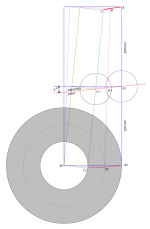
The stress on the cantilever is only the modulation of the groove (the pull by the record). However, there is a very small sidewards force at the horizontal bar on the bowl, a very small deviation of the right angle of the armtube (see the difference between point P and the centerline of the armtube: https://4.bp.blogspot.com/-Ml2I8hy1kQY/UzBA3FwT2TI/AAAAAAAAApg/YaiClo3u4Bo/s1600/rp.png). It is about 0,0005 x VTF (1,5 gram) = 0,00075 gram. So there is stress but it is nearly zero.
Changing the angle of the horizontal bar is changing the surplus force that eases the sphere to move to the other side. You have to adjust the right angle by practise otherwise the sphere will not keep the right position in relation to the tip of the stylus.
Adding weight to the sphere will result in more damping, that’s true. However, the measurements showed NO resonances of the armtube (tested from 3 to 40 Hz). So why adding mass when the only result is a slower accommodation of the right position of the sphere?
The armtube is 4 mm above the record and the brim of the bowl, so it is easy to see when the armtube is not level. Anyway, the thickness of different LP’s can differ max 1,5 mm. What do you do when you have a tangential tonearm with a very short armtube? That’s really a VTA problem and you cannot adjust it in an easy way every time at the start of a record... Suppying or subtrackting water with a bottle with a slender tube is easy.
The horizontal bar is the point where the pull of the record is active. So there is no downforce.
Sorry Directdriver, I didn't saw your post because I was revising mine.
Yes, the tonearm rotates a bit horizontally. However, to pull a solitaire sphere – filled about 30% of its volume with water – through the water of the bowl (distance 10 cm and duration 6 seconds), you need a weight of 0,06 gram. However, the music on a 12 inch record last not 6 seconds but from about 10 to 24 minutes, that’s 600 to 1440 seconds (100 to 240 times more duration).
The VTF of most cartridges is 1,5 gram, so the pull by the groove at the stylus tip is 1,5 gram (unmodulated). So the “friction” of the sphere in the water is negligible in relation to the pull of the groove at the tip of the stylus. Because the pull moves the sphere.
The stress on the cantilever is only the modulation of the groove (the pull by the record). However, there is a very small sidewards force at the horizontal bar on the bowl, a very small deviation of the right angle of the armtube (see the difference between point P and the centerline of the armtube: https://4.bp.blogspot.com/-Ml2I8hy1kQY/UzBA3FwT2TI/AAAAAAAAApg/YaiClo3u4Bo/s1600/rp.png). It is about 0,0005 x VTF (1,5 gram) = 0,00075 gram. So there is stress but it is nearly zero.
Changing the angle of the horizontal bar is changing the surplus force that eases the sphere to move to the other side. You have to adjust the right angle by practise otherwise the sphere will not keep the right position in relation to the tip of the stylus.
Adding weight to the sphere will result in more damping, that’s true. However, the measurements showed NO resonances of the armtube (tested from 3 to 40 Hz). So why adding mass when the only result is a slower accommodation of the right position of the sphere?
The armtube is 4 mm above the record and the brim of the bowl, so it is easy to see when the armtube is not level. Anyway, the thickness of different LP’s can differ max 1,5 mm. What do you do when you have a tangential tonearm with a very short armtube? That’s really a VTA problem and you cannot adjust it in an easy way every time at the start of a record... Suppying or subtrackting water with a bottle with a slender tube is easy.
The horizontal bar is the point where the pull of the record is active. So there is no downforce.
Sorry Directdriver, I didn't saw your post because I was revising mine.
Last edited:
DD, Tom
Yes. You are right. It is upforce. Anyway, I was trying to say is I am not sure once the bowl starts moving in the water. The level of arm may slight up and down. It is not stable. If it is not stable, VTA will be changed.
I don't adjust VTA for differrent LP, but I think VTA is very important and it has to be adjusted very precsiely.
Jim
Last edited:
@niffy,
A tangential tonearm moves parallel to the radian of the platter and keeps in this way the stylus at right angles to the spindle. A linear tonearm doesn’t move parallel.
You are completely right, the cartridge has to move from the outside to the inner side of the record. The opposite direction is possible but not without turning the bowl (not practical).
“Does this arm actually stay tangential whilst tracking eccentricities?”
The eccentricity of a record is mostly about 0,3 mm. So the to and fro movement of the tip of the stylus is 0,6 mm (in both directions). The tonearm cannot keep track with this deviation of the right angle but that’s no problem because it is impossible to hear. The result of this deviation is a very small difference of the amplitudes of frequencies between both channels. We cannot hear a difference of a millisecond or less between both channels during 1 rotation of the platter.
“Also the driving force to move the arm across the record is said to be purely due to the frictional drag of the stylus.”
The outer wall of the groove don’t push the tip of the stylus to the inner side of the record. That’s easy to see because the sphere shouldn’t move at all when the outer wall is responsible for the movement of the cartridge.
The angle of the horizontal bar depends on the VTF. The purpose of this angle is only to facilitate the movement of the sphere to the inner side of the record. The “roller bar” under the armtube cannot move sidewards when the angle is zero degrees.
“Have I missed something subtle in the design?”
No, but the reason that everyone is so keen to get the right tracking angle is because of the fixed pivot tonearms. That kind of tonearms is like a straight jacket for the cartridge. It causes resonances in the armtube between pivot and stylus and this is amplified too because of the angle between armtube and headshell. When the cartridge has freedom to accommodate to every alteration all these problems vanish.
“The water damping will have very little effect on armtube resonance.”
Well, tested between 3 and 40 Hz the test program (Adjust+ Pro) cannot measure any resonances (0 db). Besides that, it isn’t a very long armtube, only 120 mm to the brim of the sphere. Read the start of https://xyplo.blogspot.nl/2016/10/b-making-of-tonearm.html.
“Having such a small counterweight set such a long way behind the pivot will result in the arm having a very high effective mass and is therefore probably only suitable for low compliance cartridges.”
I have tested the tonearm with different kind of cartridges (MM and MC) and different VTF (from 1 gram to 2,6 gram). I couldn’t find/hear any malfunction. On the contrary, every cartridge sounded quite balanced (low-middle-high frequencies). However, expensive MC cartridges show far more detail.
When you push the counterweight in the direction of the sphere, the mass must increase a lot to get balance (- VTF). Moreover, the point of vertical ballance will now differ from the point of horizontal ballance. However, the metal tonearm wiring isn’t 100% flexible so it is important to reduce the horizontal trajectory of the tonearm wiring. That’s why the counterweight is 200 mm from the centre of the sphere.
“Try floating a pingpong ball in a tub of water, as soon as it gets closer than about half an inch it snaps to the side.”
True. So don’t use a metal bowl with a plastic sphere. The inner side of the bowl must be plastic or acrylic too (I used an icecream tube).
Last edited:
Hi Tom,
Thanks for the in-depth reply.
When I said that the armtube was very long I was taking the dimensions from the linked sites. It appears from the diagrams that the total arm length, tip to tail, is 400mm. The diagrams are low resolution making it difficult to see the labels clearly so I may be mistaken. In the context of the arms made by the contributors to this thread 400mm is very long. Pretty much all of the arms shown here are less than half that length, my own is a quarter that length.
The resonance I was referring to is that caused by the bending modes along the length of the armtube. Typically the resonant frequency of most arms is in the 300-700hz range and is the major contributor to colouration. I would estimate that the floating arm would have a bending mode resonance towards the lower end of this scale. It is best to try and push this resonance as high in frequency as possible. The best way of achieving this is by shortening the armtube. Most of the short arms shown in this thread Will have a resonant frequency of 2-4khz. A big improvement over most arms and is why they sound so precise. In my design I managed to push the resonant frequency up to nearly 20khz. Until you've heard an arm with no audio bandwidth resonance you don't realize just how much it colours most arms.
Hope this clarifies things.
Niffy
@Niffy,
The standing resonances inside the armtube are between the stylus and the tonearm bearing (fixed pivot tonearms). The floating tonearm has a fixed uni-pivot too, the point of contact between the horizontal bar and the roller bar. Thus resonances from the stylus will affect the armtube till this point of contact. However, 4 cm in front of the point of contact is the first connection with the brim of the rigid sphere. Now most of the resonances are travelling between the stylus and the brim of the sphere (12 cm). All these resonances are absorbed by the water because of the big surface area of the sphere into the water of the bowl.
At the other side of the point of contact – the counterweight part of the armtube – is another rigid connection (the second brim of the sphere). Thus it isn’t likewise that there are resonances between the short 8 cm part of the tonearm between the 2 brims. The last part – 16 cm to the end of the armtube – cannot resonate because there is no source of resonances (any more).
Measuring the resonances of the armtube above 40Hz shows the large peak of the frequency from the source (test record) in the test diagram. But there is a very small amplitude visible at the first harmonic. That’s all (“clean” to the end of the spectrum at 20 kHz). When I adjust the tonearm a bit “out of azimuth”, the diagram of the measurement shows more amplitudes, especially the second harmonic. That is why I assume that the resonances of the first harmonic are not in the armtube but in the cantilever of the cartridge. I have tested the cartridge very carefully and it showed that the coils at the end of the cantilever and the stylus are not perfect in line (not 100% symmetric; the deviation is about 1,5 degrees).
Of course I have tried to adjust the tonearm in such a way that there is no amplitude of the first harmonic any more. Unfortunately, I cannot “wipe out” the small amplitude of the first harmonic completely, because of the “automatic” azimuth. The tip of the stylus tries constantly to get a perfect vertical position so the friction at both sides of the tip of the stylus is identical. However, the end of the tube of the cantilever is fixed into the housing. So the cantilever will get a bit torque and will resonate easily. Unfortunately you cannot find that kind of perfect cartridges everywhere. Most of the moderate MC cartridges have some kind of asymmetry.
Last edited:
@Niffy,
The standing resonances inside the armtube are between the stylus and the tonearm bearing (fixed pivot tonearms). The floating tonearm has a fixed uni-pivot too, the point of contact between the horizontal bar and the roller bar. Thus resonances from the stylus will affect the armtube till this point of contact. However, 4 cm in front of the point of contact is the first connection with the brim of the rigid sphere. Now most of the resonances are travelling between the stylus and the brim of the sphere (12 cm). All these resonances are absorbed by the water because of the big surface area of the sphere into the water of the bowl.
At the other side of the point of contact – the counterweight part of the armtube – is another rigid connection (the second brim of the sphere). Thus it isn’t likewise that there are resonances between the short 8 cm part of the tonearm between the 2 brims. The last part – 16 cm to the end of the armtube – cannot resonate because there is no source of resonances (any more).
Hi Tom,
When a number of components are rigidity coupled together they no longer act as individual items but as a complete system. In this case cartridge, headshell, armtube, sphere and counterweight. The thin plastic of the sphere will by itself have little effect on the bending modes of the entire system/structure especially when you take into account that the armtube itself is in a single piece that passes from headshell to counterweight. It is true that the water will help to damp the system but it will not eliminate resonance. The bending modes will exhibit along the entire length of the armtube, the modes will be shaped by masses and damping attached to and inherent in the armtube but not eliminated by them unless they are very massive and rigid, eg a heavy concrete block. Unfortunately the sphere, in itself, is nether rigid or heavy enough to have much effect.
The problem with visualizing how a system such as a tonearm behaves is that we tend to think in static pictures only considering one component at a time at one point in time. The trick is to be able to picture a complete dynamic system moving through time. With a tonearm this is particularly difficult as the frequencies involved are much higher than we can visualize and the displacements and angles involved vastly smaller than any of our senses can detect. We are talking nanometers, fractions of an arcsecond being the difference between an ok arm and a great arm.
Unfortunately pretty much everything in the quote in not true.
Again I stress that I really like the whole floating arm concept and admire the ingenuity of its design. It's difficult to discuss possible flaws constructively without sounding derogatory and critical.
Niffy
@Niffy,
When the shape and different parts of an object are complicated it is handy to simplify the whole situation and cut imaginary the object into different parts to look at their individual main properties. However, when I understand your post well, you don’t trust this simplification of reality.
Well, that’s no problem. I will describe the situation again in more detail.
When I touch one of the 2 legs of a resonating tuning fork the tone will disappear nearly immediately. Not because I forced the metal of the tuning fork to stop vibrating, but because my contact dispatches energy from the tuning fork into my body. Resonances are caused by atomic/molecular vibrations because there was a transfer of energy to the resonator before.
The transfer of energy between the atoms/molecules of different materials are caused by contact (“bouncing”). So different materials can adsorb their mutual energy dispatch. Moreover, every rigid object has a resonance/ synchronous vibration at a certain frequency but not all the rigid objects resonance at the same amount of energy transfer. Now the configuration of the atoms/molecules of the material is the cause of the differences between them (atomic/molecular lattices) when the objects have the same shape and size.
The cross section of the tonearm shows a complicated object. Their is nothing to find that can act like an amplifier of resonances. Most of the object is made of a composite material (carbon fibres + epoxy) and there are no open spaces inside the object that can act as a resonant/reverberating cave (standing waves intermediated by the enclosed air). The only exception is the sphere.
The vibrating cantilever of the cartridge is a source of constant vibrations so there is a constant “stream” of atomic/molecular bouncing in the direction of the headshell and the armtube. We cannot measure any resonances with the help of the output signals of the cartridge when the resonances of the tonearm are not reflected into the direction of the cantilever. So the situation becomes complicated.
There is a specific resonance frequency of the tonearm that can affect the cantilever by the intermediating headshell and cartridge body, and there is a reflecting vibration – even when the armtube isn’t in “self resonance” – when somewhere along the armtube the vibrations are reflected. A point of reflection is an alteration of the shape, an attached part, etc. The more rigid this reflection point in relation to the armtube, the more energy will travel back.
The energy of the vibrating cantilever is absorbed constantly by the mass of the tonearm. Because it is done by atomic/molecular “bouncing” the energy will despatch to all the materials/parts of the tonearm. So at the end of the headshell the energy transfer from the cantilever will split into the inner tube and the outer tube of the tonearm. Both tubes have their specific “self resonance” but these resonances are pulled down by the Styrofoam between both tubes.
The inside of the inner tube isn’t empty. There are 4 PTFE tubes that fit exactly the inner diameter of the carbon tube and every PTFE tube is filled with 20 copper wires. The copper wiring is part of the tonearm so it dispatches energy out of the tonearm. Conclusion: the inner tube cannot resonate at all. It is like the touched leg of the tuning fork, described above. So the only part of the tonearm that can cause troubles, is the outside tube, sphere and counterweight.
When we assume that the outer tube of the tonearm can create self resonate by the vibrations of the cantilever of the cartridge – in spite of the Styrofoam – we assume that there is no energy dispatch from the outer tube. Fortunately, the armtube is dispatching resonances to the water molecules. A sphere is the most rigid shape in the universe, so the only way to resonate the armtube is by vibrating the water surface. I won’t get into all the details but a fluid transforms the “bouncing” energy partly into molecular rotations and inside vibrations. And there is an enormous amount of water molecules that have to be put in extended vibration by that small moving cantilever of the cartridge.
What about the reflecting vibrations? Because the contact point between the horizontal bar and the roller bar is quite massive in relation to the first part of the outer arm tube. Vibrations that have passed the first brim of the sphere are partly reflected by this contact point (metal). The other part arrive at the second brim of the sphere and will lose most of their the energy to the water. The residual frequencies have to pass the first brim for the second time in reverse direction. And again most of the energy will be dispatched to the sphere and the water. So hypothetically there are some vibrations that will reach the cantilever again but there is not enough energy left to influence the movements of the cantilever.
There is a possibility to measure the vibrations of the outer armtube with the help of a laser that reflects on a very small mirror, attached on the outside of the armtube. The reflected laser beam have to be caught by a photon receiver and when the output signal showed to be a frequency, it is proofed that there is self resonance. That’s not a simple task.
- Home
- Source & Line
- Analogue Source
- DIY linear tonearm