Gate drive seems to work fine in simulation, i wil try it with the amp i designed and probably build it
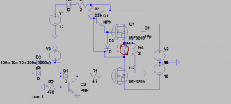
Hi,check my simple driver,not best but good enough 😱
Place 2R2 in series with diode on 12V,to limit current peaks.
same schematic as yours,without amp circuit,2k2 resistor., D1 encounters 12a peak at start for 7 us
It works well with split supply in simulation,with very hard to drive mosfets,but i dont like the 8 A on d4 in my schematic,i would dissipate more power than anything
Attachments
Last edited:
Can you see that slow start up edge on upper gate?
I use Multisim,result is same as in practice.I try to make better driver,but without results 😀
With resistor drive is much better,but dissipation is cca 6W (with max duty it's 12W!)
I use Multisim,result is same as in practice.I try to make better driver,but without results 😀
With resistor drive is much better,but dissipation is cca 6W (with max duty it's 12W!)
What about reversed PNP?It works well with split supply in simulation,with very hard to drive mosfets,but i dont like the 8 A on d4 in my schematic,i would dissipate more power than anything
Yes,it will dissipate more than fets 🙂
I'll try another idea...
Yes,but 100n series cap. may have resonance at audio freq.
Now tried with opto (HCNR200) and output is same as input 😀
Now tried with opto (HCNR200) and output is same as input 😀
And maybe IR2184 with separated power for upper and lower fet (small flyback smps)...I dont think there are better options than gate drive transformer
You said you can get 3kw from ee42.,my calculator says maximum of 800w, how could you determine that you can get 3kw?
Check my new progress 🙂
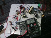
Class D on +/-56V 500W SMPS working now,with feedback,offset 1,8mV 😉
Do any interested 😀
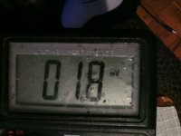
First pic. voltage measuring. (Left meter lies,chinese s*it) Both voltages is same.
Last pic. offset
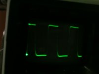
Second pic. wave after totem pole
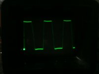
Third pic. is voltage at drains of fets.
Fourth pic. is voltage at SMPS transformer.
Class D on +/-56V 500W SMPS working now,with feedback,offset 1,8mV 😉
Do any interested 😀
First pic. voltage measuring. (Left meter lies,chinese s*it) Both voltages is same.
Last pic. offset
Second pic. wave after totem pole
Third pic. is voltage at drains of fets.
Fourth pic. is voltage at SMPS transformer.
Attachments

Last edited:
- Status
- Not open for further replies.
- Home
- Amplifiers
- Class D
- DIY Good Class D amplifier