what is the maxx +/- ? voltage to be used at what impedance? also what are the output transistors used?
Output transistors can be anything i guess, i would recommend irf4227, max voltage should only be limited by fets and regulator
Yes,limit is FET voltage.I use IRF640N,BUZ60 and IRFZ44N and all works OK and cold (only BUZ can get little warm).Gate drive FET can be any same or voltage as outputs,min. 4A,with smaller Qg.
Here's schematic without transformer.
470p...2n2 to change frequency.
Here's schematic without transformer.
470p...2n2 to change frequency.
Attachments

Last edited:
Max +/-90V I recommend.Impedance vary with FET's,for more power use two in parrallel,each with our own 1n4148/UF4007 and 56R at gates.what is the maxx +/- ? voltage to be used at what impedance? also what are the output transistors used?
I tested both IRFZ44N and IRF640N,and tried small BUZ60,but it has little warm because of high Rds_on.
Yes,tested on +/-56V,offset cca. 8mV.Out direct to diferential pair?
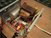
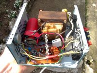
My friend make my amp from post #268 and he say it's very loud and has high power.He use 48VDC as power and now test on 2 ohm load:
Attachments
Last edited:
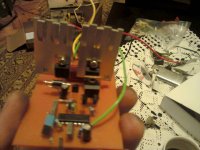
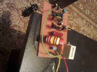
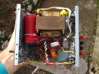
Completed amp from my friend,he says it's great for he 🙂
Attachments
-
 post-316-0-99391000-1391966936.jpg44 KB · Views: 278
 -
 post-316-0-53708700-1391968516.jpg39.5 KB · Views: 257
 -
 post-316-0-48547300-1391966838.jpg32 KB · Views: 279
 -
 post-316-0-30671800-1391966830.jpg38.8 KB · Views: 295
 -
 post-316-0-22407000-1391966943.jpg43.7 KB · Views: 273
 -
 post-316-0-14480100-1391966846.jpg39.1 KB · Views: 292
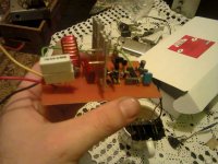
This is amp what my friend make.I forgot 1u input cap on schematic,it's placed in series with input and 1k resistor.Succesfull tested at 1ohm and 50V supply by me.When he make video I'll send link here.Simple Class D for begginers,version 2 (better),with pcb 😎:
Single,later used 110V (two 55 in series) but it has cooling problem on 1 ohm because current is high (peaks is over 30A,which is more than my fet's can handle,I use four IRF640)
If use fets in parallel,change BC639 and 640 with BD139/140 and make each fet has own gate resistor and diode.
If use fets in parallel,change BC639 and 640 with BD139/140 and make each fet has own gate resistor and diode.
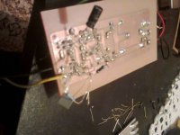
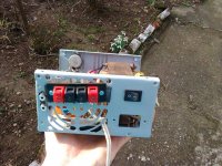
And this is amp for PA,not for Hi-fi,friend says a mid's has lower volume than high's and bass,instead of TDA7294 but this can be corrected with changing value of input cap parallel with 47k and parallel with gain resistor (I suggest him simple circuit to get more gain,only cut pins 2 and 3 and make classic amplifier like opamp.- input is pin 2 and out is pin 3.Only add 10u to 100u cap from ground in series with 1k to pin 2 and use parallel RC (R is for gain,470R to 10k or more if needed,C is 47p to 100n,for filtering) placed to pin 2 and 3.
And this is amp for PA,not for Hi-fi,friend says a mid's has lower volume than high's and bass,instead of TDA7294 but this can be corrected with changing value of input cap parallel with 47k and parallel with gain resistor (I suggest him simple circuit to get more gain,only cut pins 2 and 3 and make classic amplifier like opamp.- input is pin 2 and out is pin 3.Only add 10u to 100u cap from ground in series with 1k to pin 2 and use parallel RC (R is for gain,470R to 10k or more if needed,C is 47p to 100n,for filtering) placed to pin 2 and 3.
please draw a simple schematic to explain the modification above.
and how is the clarity of this amp compared to irs 900d ,also is it silent or does it have switching noise issues?
Ok,I'll post later.
I don't know,i never see or listen irs900d,it's silent on speaker,only i can hear small "sssssss" on headphones.When power with smps there's small noise,because freq. is similar,but I'll fix it.
I don't know,i never see or listen irs900d,it's silent on speaker,only i can hear small "sssssss" on headphones.When power with smps there's small noise,because freq. is similar,but I'll fix it.
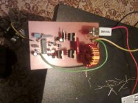
Completed amp from friend,gain and schematic that i currently use (better than 494 in all cases):
Attachments
-
 Klas D3_SG3526.GIF20.7 KB · Views: 777
 -
 post-316-0-60557100-1392034227.jpg69.4 KB · Views: 876
 -
 post-316-0-52846400-1392034330.jpg72.8 KB · Views: 831
 -
 post-316-0-44529600-1392034237.jpg65 KB · Views: 848
 -
 post-316-0-18377200-1392034248.jpg63.4 KB · Views: 897
 -
 post-79-0-95037800-1391849020.gif3.5 KB · Views: 945
I test IRFP260 here,but you should use BD139/140 instead of BC.
Supply is limited by fet's,if use higher voltages place driving fet (T6) to heatsink too.This fet can be another cheaper FET,like IRF6xx or IRF740.I use there worst case FET,IRF840 (high Qg and capacity).With better FET overal amp only can get better.You can vary resistors in gates (R6 and R12) from 10 to 100R,but use one that heating of fet's is minimal,but not too high,because of slow gate drive.
Supply is limited by fet's,if use higher voltages place driving fet (T6) to heatsink too.This fet can be another cheaper FET,like IRF6xx or IRF740.I use there worst case FET,IRF840 (high Qg and capacity).With better FET overal amp only can get better.You can vary resistors in gates (R6 and R12) from 10 to 100R,but use one that heating of fet's is minimal,but not too high,because of slow gate drive.
Hello,check small test from my friend 😀
Klasa D sa TL494,mali test - YouTube
When power up,telephone microphone is overdriven and this is reason why it distort signal.
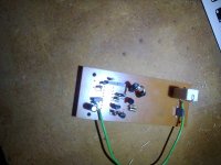
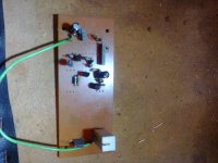
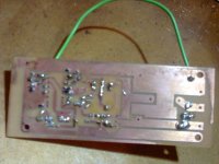
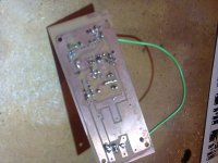
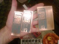
And my friend make few PCb's for me (for SG3526):
Klasa D sa TL494,mali test - YouTube
When power up,telephone microphone is overdriven and this is reason why it distort signal.
And my friend make few PCb's for me (for SG3526):
Attachments
Last edited:
Simple amp for begginers,and test of my amp on +/-55V,meter on speaker shows AC output at 4 ohm load.
I was impressed with this amplifier !
I'll test. Unfortunately I do not have oscilloscope, but I want to want to decrease switching frequency (RT,CT) and hope to see using software like Visual Analyzer 8.30.21
- Status
- Not open for further replies.
- Home
- Amplifiers
- Class D
- DIY Good Class D amplifier