Has anyone used the FE to turn any of the diy pass amps balanced?
I’m thinking of building an F4, use the 24V power supply in the chassis, and wire up a balanced input with option to use rca as well and the full 20db gain.
I’m thinking of building an F4, use the 24V power supply in the chassis, and wire up a balanced input with option to use rca as well and the full 20db gain.


I'm using a 2022 FE to drive a M2 OS, similar to (but not the same as) what EUVL is doing in the thread The M2 Output Stage in Class A/B, and maybe a Power WHAMMY? with no global feedback around the output stage. Recently I made some distortion measurements with REW at an output level of 2.8 VRMS. I was bit surprised to find that H2 was about -85 dB at the output (C3 on the original schematic), which is somewhat higher distortion than what Nelson suggested is possible with the circuit.
What I found is that the 2022 FE is somewhat sensitive to output loading. Nelson's article showed distortion with a 10k load. The M2 OS presents a load of roughly 23.5k. Eventually I settled on adding a 6.8k resistor between the R5/C3 node and ground, for an effective load of about 5.3k. This dropped the H2 to roughly -95 dB, with noticable and worthwhile audible effect. H3 remained fairly constant at roughly -104 dB, give or take a bit, throughout the various tests.
The morals of this story are:
1. REW is your friend.
2. It can be worthwhile to experiment with output loading.
I would have thought that the distortion would be lower with a higher impedance load.
Did you do your distortion measurements with the DIY FE connected to the M2 OS? If yes, then perhaps the higher than expected distortion is due to the output capacitor of the DIY FE being in series with the input capacitor of the M2 OS, resulting in a combined lower capacitance, which affected the measured distortion of the DIY FE.
You can do a test by measuring the distortion of the DIY FE standalone with load resistors of 10K and 5K.
That would have been my initial thought as well.
I did duplicate the initial measurement with a standalone FE, but the final measurements were taken in the assembled amp. In this case, the output capacitor of the FE is the input capacitor of the M2 OS (there is only one, C3 is shorted on the FE board and I'm using a 4.7 uF film cap at the C2 position on a Tea-Bag M2 board). The impedance of the 4.7 uF cap is effectively zero at 1kHz, where I took the measurements.
But don't take my word for it.
I don't take sims results too literally, especially WRT distortion estimates. I think measurements of actual hardware will be better.
Enjoy the daylight. It is already dark here.
Enjoy the daylight. It is already dark here.
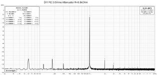
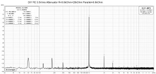
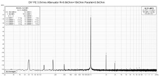
Measurements done: Vout=3.0Vrms at 9.8kOhm, 6.6kOhm, and 5.0kOhm.
9.8kOhm was the attenuator only (diy from schematic on Akitika website), 6.6kOhm= attenuator + 20kOhm resistor, 5.0kOhm=attenuator+10kOhm resistor.
Distortion increased as impedance dropped.
9.8kOhm was the attenuator only (diy from schematic on Akitika website), 6.6kOhm= attenuator + 20kOhm resistor, 5.0kOhm=attenuator+10kOhm resistor.
Distortion increased as impedance dropped.
Attachments
That's interesting. Definitely not the pattern I saw. In fact, your first plot where H2 = 0.00064% (-103dB) is significantly better that any of my measurements. Are you using the V0R1 board with the 10R R13 degeneration resistor for Q5? That could possibly explain the difference in our results. I am using the original V0R0 board.
I got these load vs. H2 values:
I got these load vs. H2 values:
- 23.5k -86.3 dB
- 10.8k -88.3 dB
- 7k -91.8 dB
- 5.3k -95.6 dB
- 3.9k -84.7 dB
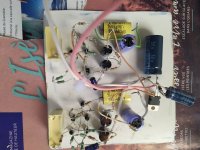
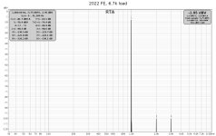
Still confused. I retook the measurements, this time using a standalone FE. Got better results, but still indicating the same trend.
The setup is bipolar supply @ +/- 23V, no capacitors, load connected from R5 to ground. Output at 2.9 VAC.
The setup is bipolar supply @ +/- 23V, no capacitors, load connected from R5 to ground. Output at 2.9 VAC.
Attachments


I understand getting rid of the input and output coupling caps when you know you can get away with it, (source already blocks DC, circuit being fed has it's own coupling cap, etc.) But I always use a cap in the feedback leg, C2 in this case to block DC, no matter SE or balanced in. Just an observation..
I think the DC offset issues are manageable. In the amp the FE is cap coupled to the OS so as not to disrupt the bias circuit.
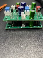
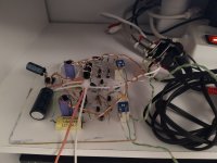
No box yet. But could not resist and fired it up 😀
It works! Could not really evaluate it, because I listened for just a few minutes. But the first impression is that of a nice and clean sound. Neither "warm" nor "cold" but still not "clinical".
Will do some more listening tomorrow...
It works! Could not really evaluate it, because I listened for just a few minutes. But the first impression is that of a nice and clean sound. Neither "warm" nor "cold" but still not "clinical".
Will do some more listening tomorrow...
Attachments
Hi Marcus,
Looking at your post #1,295 I have some thoughts that may or may not affect the distortion measurements:
1. I assume you are not using an attenuator to attenuate the signal into the Focusrite since I see the Focusrite input level set at Minimum. That may affect Focusrite distortion level.
My setup has an attenuator so that I can set the input level knob at about 11o'clock. From what I have read, that is a good position for best performance of the Focusrite.
2. I see that the REW level is set at approximately -2dB. That may be too high and close to overloading REW/Focusrite, and affect the distortion level. I aim for somewhere between -10 and -20dB.
3. My DIY FE is powered by 62V single ended and your DIY FE is powered by +24V 0 -24V. The voltage difference will affect the distortion.
4. It looks like you are using an external oscillator that is not in the picture. What is the oscillator's distortion? I use an older version of the Victor oscillator and its distortion is lower than the DIY FE's measured distortion.
I know LTSpice is only a simulation and results do not necessarily agree with reality. Having said that, I did try 62V, 48V, and +24V 0 -24V, and the lower voltage and the bipolar voltage simulations did show some erratic results.
Hi Ben,
Thanks for your comments. You are correct that I am not using an attenuator in this setup. My signal generator is another external DAC being fed sine waves generated by sox. The distortion levels of the source and Focusrite alone are visible above the noise floor but significantly lower than what's being generated by the FE. I'm just getting some experience with the Focusrite and REW and appreciate the tips.
Thanks for your comments. You are correct that I am not using an attenuator in this setup. My signal generator is another external DAC being fed sine waves generated by sox. The distortion levels of the source and Focusrite alone are visible above the noise floor but significantly lower than what's being generated by the FE. I'm just getting some experience with the Focusrite and REW and appreciate the tips.
- Home
- Amplifiers
- Pass Labs
- DIY Front End 2022