Has anyone else other than Lhquam in post 401 used the virtual ground that Nelson Pass mentions in the DYI Front End 2022 article that can be used with a single-polar power supply? Lhquam mentioned that he experienced humming with it. I intend to use a bipolar supply but am curious what people may have experienced with it and also in any techincal articles or discussions addressing the virtual ground that would result as executed as Nelson Pass suggests.
I would like what’s behind link #4, Monty….🤣
I've never tried the RK501, but if you can live with 21 steps I like the chinese “Dact Type” pot better than either ALPS. They also can be found in an audio taper style.
I've never tried the RK501, but if you can live with 21 steps I like the chinese “Dact Type” pot better than either ALPS. They also can be found in an audio taper style.

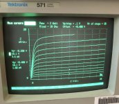
Mystery solved - my J113 is marked as Fairchild but when i checked using the Chinese Transistor checker, it showed Drain in the middle pin unlike all the datasheets showing source as the middle ( only Interfet is having middle pin as Drain). Then i realized i had tested it wrongly and to check i loaded the J113 in the curve tracer pins matching the cheap transistor checker, now I see nice curves with 3,6 mA at -0,2V VGS. I t had survived the wrong connections. Now I will check ( probably around 600 ohm range for Source resistor? ) on the test jig.
Attachments
If it’s labeled as Fairchild with the wrong pinout, wouldn't that mean the parts are suspect? And not use them?
Be careful with cheap Chinese testers. They are incredible value for the money but have some quirks.
If I put J113 in the tester at the same position, but second time rotated 180 degrees (still occupying same test contacts as first time) first time tester identifies middle pin as Source. With rotation, middle pin is identified as Drain!
If I put J113 in the tester at the same position, but second time rotated 180 degrees (still occupying same test contacts as first time) first time tester identifies middle pin as Source. With rotation, middle pin is identified as Drain!
I don't know if this is the case with j113 but some jfets have symmetric source and drain. If that's the case, your tester may misidentify them.
Hi Mark
Thanks for the links. I’ll choose one of them.
Eric
You are aware that J113 has a Drain, Source, Gate instead of the common Drain, Gate, Source pinout?The J113 having 6mA IDSS without any source resistor required 2600 ohm source resistor to bring the current below 4.4 mA! So select the J113 having lower IDSS for this duty
edit: I see I'm late to the party...
The intent is to have the resistor on the ground side shorted, otherwise that circuit does not properly filter.Has anyone else other than Lhquam in post 401 used the virtual ground that Nelson Pass mentions in the DYI Front End 2022 article that can be used with a single-polar power supply? Lhquam mentioned that he experienced humming with it. I intend to use a bipolar supply but am curious what people may have experienced with it and also in any techincal articles or discussions addressing the virtual ground that would result as executed as Nelson Pass suggests.

With quality PP or PPS film caps already at those locations, I can't imagine a small bypass cap would be necessary or noticeable. But, with DIY you get to do what you want. Stick some .1uF's in parallel and let your own brain decide if it's worth it or not. If you know with 100% certainty that the circuit in front, and behind the FE '22 is already cap coupled with no possibility of DC, then just replace those "dreadful" C1 and C3 caps with a straight piece of wire..
Beware, if the power supply is not bipolar, omitting the capacitors will send significant DC voltage out to the source and amplifier. So the source and amplifier must be capable of accepting DC voltage in addition to not sending out DC voltage. Or the safest thing to do is to leave the capacitors in place if the power supply is not bipolar.
Hi
Can someone please point me to the right place so I can place an order with Digikey. I now have pcb V0R1 but the BOM from the V0R0 doesn’t include P1, C6, R13 and R14.
What’s their value and are they needed. I’m guessing P1 is for the DC offset..
I’ll be using a small 48Vdc, 24W SMPS + SMPS filter from Mark. My input will be SE.
Thanks to everyone making these kits available.
Eric
This should help: https://www.diyaudio.com/community/threads/diy-front-end-2022.394339/post-7323986OK everybody, gird your Grids, here comes Version 1 rev 1:
I have added some additional optional parts. As you can see from the schematic there is
now an R13, R14, P1 and C6.
R13 is a low value degeneration resistor for Q5. In actual testing with the KSA992 I did
get a bit lower distortion with a 10 ohm value. Not a big deal, but it does help get me
down to sub .001% distortion numbers, even with the J113 input fets. Accompanying
that is a slight increase in R6 to 750 ohms. If you want to lowest thd numbers, use a
supply as high as +/-24V or 48V single-ended.
However, I have also included a 1 Kohm pot which can replace R6 in case you want to
make the small sacrifice of distortion vs DC offset in DC coupled applications. Just turn
the pot until the DC is zero, and adjust it again after warmup. Remember to leave R6 off.
R14 is an optional resistor if you want to take your feedback from an output stage. You
can leave R4 in if you want some local feedback. Or not. Remember that R14 looks at an
output node which might be at a different DC potential, and it might require an external
blocking cap in such a case.
C6 is a lag compensation cap in case you need one. 33 pF will not have much effect on
the distortion vs frequency plot, 100 pF will increase the thd a bit at 20 KHz, but still have
acceptable performance. When you have a weird load or take feedback from an output
stage this might come in handy.
PC board is larger by 1/4 inch, this should not be a problem. Keep in mind that these are
all options - you can easily build the original, just put a jumper across R13 with a leftover
resistor lead.
Kits are being packed up, and if they sell out, there are more coming....
I'm about to order the following caps for C1-C3 but have 1 question; https://www.digikey.ca/en/products/detail/panasonic-electronic-components/ECW-FD2W335K/4271843
These are Polypropylene type, original BOM suggested a Polyester cap but hey this preamp deserve better ;-) the only issue is that Polypropylene caps are normally bigger...
These caps are slightly bigger than the size on the PCB but I don't care for that, my concern is the diameter of the lead of these caps which is 0.8mm (according to spec sheet)
Mounting holes for these caps are rather small on the PCB, does anybody know if the 0.8mm diameter is too large ?
Thanks,
Eric
Hi Eric,
they do fit, no worries ... 😉
(I had to re-shape the legs a little bit, as the lead spacing is a bit larger than the hole distance on the PCB)
Best regards, Claas


they do fit, no worries ... 😉
(I had to re-shape the legs a little bit, as the lead spacing is a bit larger than the hole distance on the PCB)
Best regards, Claas
- Home
- Amplifiers
- Pass Labs
- DIY Front End 2022