you can't do gain lower than 1
if you wan't that, use attenuating cell and buffer
if you wan't that, use attenuating cell and buffer

and you'll kill dynamics
this circuit is not meant to drive 200R load
if you have particular needs for your signal chain, open separate thread and give all details
that way you'll end with proper solution, not as this - using inappropriate ones
this circuit is not meant to drive 200R load
if you have particular needs for your signal chain, open separate thread and give all details
that way you'll end with proper solution, not as this - using inappropriate ones
Could this circuit be used as part of IV stage for a DAC with balanced output? E.g. Sabre ES9028. Any concerns, disadvantages?
Last edited:
Of course, I/V conversion can be done by a resistor. Some DACs are V out so only gain stage is required if I understand it correctly.
I believe that when we decide what to build, our choices are driven by the overall experience and how a component brings us joy.
This feeling comes not only from the sound of the music but also from various other factors. It is a highly personal and individualized process.
We choose to build an amplifier when it satisfies our emotional preferences and when we develop a deep attachment to it. Do you agree?
In my view, the preamp is comparable to the core of an audio system.
I would be interested to hear about your sound experiences with FE2022.
I can't speak for the FE '22 (yet) but Papa has mentioned before that very simple circuits, that also happen to measure well, have a very good chance to also sound really good. I definitely agree. The experience as a whole, is affected by so many things. Examples like synergy between the amp's output stage and the speakers. The character of the speakers themselves and the room acoustics along with the particular speaker and listening position within that space. Single ended vs push-pull. The systems gain structure and noise level. How the volume control is implemented. Feedback or no feedback, and how much, and is it local or global. The manner in which the voltage gain is derived... what active devices?.. the VAS has a huge effect on the character overall.. What are the operating points? Maybe a transformer is implemented that adds some of it's own character. Current mirrors, cascodes, current sources, bootstrapping... it all matters to some degree. Degeneration or not? How much and where is it used? Does the circuit require compensation for stability? Is it simple miller comp or something more advanced? More complexity, more parts, better THD-1 / THD-20 does not automatically mean better sound IMO. How good is the quality of the source, both the hardware and software? What is your mood? How intoxicated are you? And a million other things I'm forgetting or am ignorant of myself.. The learning never stops. Just have fun and enjoy the ride....
Last edited:
William2001, I read your near complete enumeration of all possible check states with pleasure and asked myself - you already know all this and try to implement and evaluate all of them. And of course the fun is so great that I'm curious if other GB feel the same way.
From my experiences and listening sessions I can only report that the FE2022 impresses me in some ways:
1. It has a balanced frequency response, reaching deeper lows without an excessive emphasis on upper bass. It also maintains a flat response in the presence and super high-frequency regions.
2. My build is exceptionally quiet, which enhances its ability to capture fine details, N + THD < -90dB using single rail 48V SMPS
3. It shines in creating a realistic soundstage, with a black background that allows the sounds to stand out with clarity and precision.
4. Last but not least, my build has a wide volume control range from 0 to 80 steps, making it highly functional. This is visually displayed and realized with an 10k APLS pot. Max gain is limited to 6dB, with R3 = R4 = 20k
I have one small suggestion for improvement, i. e. three mounting holes with lead spacing = 5mm for C1, C2 and C3 on next PCB release. The existing holes on PCB V0R1 have 7.5, 10 and 15mm grid for these. I used tiny Wima MKS2 3.3uF 63V which need 5mm
Dear Gents,
I started filling my newly aquired FE board from the DIT Store and did not noteice there are other components that are not in the previous board.
I filled and followed the BOM from Papa's article.

Then ended up with a few missing parts. I would appeciate if I can be guided on with component values that goes in the board as highlighted:

1. R 14 and R 13 ? (yellow) I am not sure if they are the same value?
2. P1 ? (pink)
3. C6? (orange)
Thanks in advance.
I started filling my newly aquired FE board from the DIT Store and did not noteice there are other components that are not in the previous board.
I filled and followed the BOM from Papa's article.
Then ended up with a few missing parts. I would appeciate if I can be guided on with component values that goes in the board as highlighted:
1. R 14 and R 13 ? (yellow) I am not sure if they are the same value?
2. P1 ? (pink)
3. C6? (orange)
Thanks in advance.
If you want to just use the original V0R0 version parts in the V0R1 board, just ignore P1, R14, and C1 (leave empty), place a wire jumper in the R13 position, and install the original 680 Ohm resistor in the R6 position.
Attachments

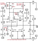
A diyAudio member messaged me asking about the selection of J113s. My understanding is that they were selected based on their CCS performance, namely Q3 with 332R source resistor for a little under 3mA, and Q4 with 100R source resistor for a little under 9mA.
Post #18 - CCS Currents
Post #20 - CCS Currents
Post #18 - CCS Currents
Post #20 - CCS Currents
Relative to the other Fairchild types still available, the J113 seems to have an Idss that is actually measurable when matching devices, or around 24mA in my experience. The Idss "minimums" on those Fairchild data sheets are almost meaningless. The J111 and J109 typically have Idss >100mA, for example.
As to the reason NP used them as CCS, I would guess he wanted to keep the same part as for the diff pair, for economy of BOM and prolly because he has so many.
As to the reason NP used them as CCS, I would guess he wanted to keep the same part as for the diff pair, for economy of BOM and prolly because he has so many.
Yes, I have about 300,000 of them. They aren't particularly special, but they
hold up to 70V and they have a decent transconductance figure and aren't very
noisy. I select them by Vp, which reliably translates to Idss and a chart I made
up of CCS current vs Vp vs resistance. Also they come with formed leads which
halves the effort to test them....

hold up to 70V and they have a decent transconductance figure and aren't very
noisy. I select them by Vp, which reliably translates to Idss and a chart I made
up of CCS current vs Vp vs resistance. Also they come with formed leads which
halves the effort to test them....
I am familiar with Erno Borbely's articles and saved everything I could from his now defunct web site. I have yet to find a practical circuit to measure Vp, as it is not a single value but a voltage range.
For those unfamiliar with Mr. Borbely's work I have linked below the article you mentioned.
https://audioxpress.com/article/JFETs-The-New-Frontier-Part-1
https://audioxpress.com/article/JFETs-The-New-Frontier-Part-2
For those unfamiliar with Mr. Borbely's work I have linked below the article you mentioned.
https://audioxpress.com/article/JFETs-The-New-Frontier-Part-1
https://audioxpress.com/article/JFETs-The-New-Frontier-Part-2
That's odd. The course textbook for semiconductor physics, at least when I took as a first year grad student (here's a link), defined a JFET's Vp unambiguously: Vp .=. Vgs which gives Ids = zero plus epsilon . . . . textbooks may have a different definition of "epsilon" than you do or than the late Erno Borbely did.
The manager of our device modeling group in a for-profit design company, chose epsilon := (Idss / 1E+5). But she is not you and vice versa!
The manager of our device modeling group in a for-profit design company, chose epsilon := (Idss / 1E+5). But she is not you and vice versa!
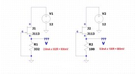
grimberg, If your goal is to sort some J113 for the DIY FE 2022, you can set up the J113 circuit and measure the voltage drop of the source resistor.
Out of curiosity I measured the J113 source resistor voltages of one of the channels of my DIY FE 2022, R8 was 0.95V (0.95V/100R = 0.0095A) and R7 was 1.4V (1.4V/332R = 0.0042A), so 9.5mA at the output stage and 4.2mA at the input stage - close enough.
Out of curiosity I measured the J113 source resistor voltages of one of the channels of my DIY FE 2022, R8 was 0.95V (0.95V/100R = 0.0095A) and R7 was 1.4V (1.4V/332R = 0.0042A), so 9.5mA at the output stage and 4.2mA at the input stage - close enough.
Attachments
- Home
- Amplifiers
- Pass Labs
- DIY Front End 2022