Thanks but if you look carefully that schematic is not the right one. I already have that schematic.
Yes, I've noticed that. Even this scheme I asked three times from the seller. Seems like they don't like to share this info 🙂.
No problem. I have used half of board to supply diyhink es9018 or audiodesunie es9018 dac . Both have i2s input.
But now I must do some reset in my head. After i tested or listen to TOTAL DAC d1 twelve, this two dacs are not interesting anymore. Total dac is dammmm realistic and analogue sounding but the price is 🙁
But now I must do some reset in my head. After i tested or listen to TOTAL DAC d1 twelve, this two dacs are not interesting anymore. Total dac is dammmm realistic and analogue sounding but the price is 🙁
Hi oneoclock,
I want to try out what you did with lowering the voltage down to 5v.
Is it possible for you to make a quick drawing, or explaining how you did it?
-usbdac
I want to try out what you did with lowering the voltage down to 5v.
Is it possible for you to make a quick drawing, or explaining how you did it?
-usbdac
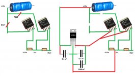
Hello Androa:
The two outputs AMS1117-1.2 V: 242 and 288 Oh. (5 mA).
The DAC comes with a 9 V + 9V transformer for digital sources.
One 9 V. provides 13.8 V at the input of LT1963 + 2x AMS1117.
Other 9 V. for the 7805 and LM317 + ADP150.
LT1963 digital cooler than analogs.
Now both analog LT1963 14.3 V. before, now 5V.
Hello Damuffin:
I have the finished the DAC. The sound is better than others DAC I have. The LT1963 regulators are very good. I have done measure at all points of the DAC and is running fine after correcting dissipation problem.
It is difficult to replace with trident without damaging DAC if there is no problem to solve.
I purchased 6x AD797B in RS.
I put in the weilliang DAC. Measures are identical to 6x AD797ANZ received from Weilliang Chinese manufacturer.

I think the AD797ANZ received from Weilliang are originals. And oscillate in the circuit I / V like AD797B. Also original RS AD797B oscillate. But they work very well in the output Bal / SE.
I have found that the 4x I / V is very hot AD797B like AD797ANZ. And 2x output buffer balanced to SE no hot AD797B like AD797ANZ.
4x I/V OPA604 is not hot.
2x Bal/SE AD797 measures is better than 2x OPA204 or 2x LME49710 with 4x I/V OPA604.

I put in the weilliang DAC. Measures are identical to 6x AD797ANZ received from Weilliang Chinese manufacturer.
I think the AD797ANZ received from Weilliang are originals. And oscillate in the circuit I / V like AD797B. Also original RS AD797B oscillate. But they work very well in the output Bal / SE.
I have found that the 4x I / V is very hot AD797B like AD797ANZ. And 2x output buffer balanced to SE no hot AD797B like AD797ANZ.
4x I/V OPA604 is not hot.
2x Bal/SE AD797 measures is better than 2x OPA204 or 2x LME49710 with 4x I/V OPA604.
I have been playing with the outputs on the four layer and have noticed that the balanced output is filterless and the SE opamp socket pin2- pin3+ have an rc filter. It has 470 ohm resistor and the 104 cap marked 15j. If this is a 15nf cap it will be crossing over at 22k. I am thinking of upping it to 40-50k to bring back the sparkle that it's eliminated.
380r - 8.2nf = 50k, looks like a popular alternative.
Theres also a compensation cap in the I/V feedback, its 100p in series with 100r. Whats the purpose of the 100r?
Anyone try the lme49990 as I/V yet? I love it without the poorly implemented SE that follows.
380r - 8.2nf = 50k, looks like a popular alternative.
Theres also a compensation cap in the I/V feedback, its 100p in series with 100r. Whats the purpose of the 100r?
Anyone try the lme49990 as I/V yet? I love it without the poorly implemented SE that follows.
Last edited:
104 will be the value of the cap in pF: 10 + 4 zeros = 100,000pF = 100nF. This will be the supply decoupling for the op-amp.
The 100pF for the I/V op-amp acts as a low pass filter. The extra 100R is to isolate capacitance between input and output of the op-amp.
I/V not tried the LME49990 as I/V, though it was very good in a bal-se stage.
The 100pF for the I/V op-amp acts as a low pass filter. The extra 100R is to isolate capacitance between input and output of the op-amp.
I/V not tried the LME49990 as I/V, though it was very good in a bal-se stage.
Ah thanks Spartacus, thats what 104 means. The 104 pcb marking has a 15j Cap in it, and is part of the crossover network.15nf-470r (22,000hz) is much to low. It is altering phase and reducing clarity. Im unsure of the quality of these components as well. What I'm recommending to everyone is to replace these components and match resistors with:
71-RN55D-F-301
505-FKP2-.01/63/5
.01uF-301r bringing the low pass to 53,000hz
I cannot find any info about isolating Ccomp. It must not be a popular implimentation.
71-RN55D-F-301
505-FKP2-.01/63/5
.01uF-301r bringing the low pass to 53,000hz
I cannot find any info about isolating Ccomp. It must not be a popular implimentation.
Hmm, perhaps in this case 104 is a part number. Anyway, 22KHz is very low, as you say, will be interesting to see how a higher value changes the sound. It's rather strange - the -3dB point for the reference design is much higher at around 100KHz.
I just found this on Wikipedia about DSD.
"All SACD players employ an optional low-pass filter set at 50 kHz for compatibility and safety reasons, suitable for situations where amplifiers or loudspeakers cannot deliver an undistorted output if noise above 50 kHz is present in the signal."
Ayre article:
"Standard DSD has low noise levels in the audio band. But at 20 kHz the noise rises sharply."…….."These high-frequency noises can lead to damage of downstream equipment including amplifiers and loudspeakers. Therefore the official Sony specification (the “Scarlet Book”) specifies a third-order low-pass filter starting at 50 kHz, and the actual usable frequency response of SACD doesn’t extend much beyond 30 kHz".
Hi guys,
question regarding output stage, I'm facing similar cut off frequency issue described in last few posts so I was thinking to use output transformers instead of unknown buffer stage, I got spare 600:600 trafos I wanted to try but not sure about proper connection and if I have to cut/add anything between I/V and transformers, I do not have same sabre DAC as mentioned in this thread neither output stage schematics so can't explain current design of it but I thought someone more experienced and knowledgeable here could help and give me some advice, maybe it's not worth it and will need to change the OS completely but if there's any chance to fix current one I would try it 🙂 , here is my current right side OS, resistors in I/V are 100R + 251R (not sure about this one), appreciate every feedback, thanks a lot...
question regarding output stage, I'm facing similar cut off frequency issue described in last few posts so I was thinking to use output transformers instead of unknown buffer stage, I got spare 600:600 trafos I wanted to try but not sure about proper connection and if I have to cut/add anything between I/V and transformers, I do not have same sabre DAC as mentioned in this thread neither output stage schematics so can't explain current design of it but I thought someone more experienced and knowledgeable here could help and give me some advice, maybe it's not worth it and will need to change the OS completely but if there's any chance to fix current one I would try it 🙂 , here is my current right side OS, resistors in I/V are 100R + 251R (not sure about this one), appreciate every feedback, thanks a lot...
I tried a 600:600 transformer and it worked poorly when connected directly to the 9018, but sounded ok after the I/V op-amps as a BAL-SE converter. IMHO I don't think it is worth the expense.R834,844,841,832 are part of the RC filter. So a 301r value will bring the filter up to 53,000kHz, and be sure to match the values as close as possible.
thanks a million damuffin, I will check at home what are current values of these 4 resistors, nothing to change in I/V? I got those LL1527 available so I could use them just to try it but if you did already (with I/V) and the result wasn't better than standard op-amp stage than I will leave that idea, thanks again...
If you have some solid cat-6 wire you can tin it up and connect your transformer into pin 2 and 3 (-+ signal) on the dip 8 socket marked c806,c805. Try it, you might like it. Also use a LME49990 for I/V. LME49710 is less fussy if your circuit can't keep the 49990 stable. ( These are all single channel op-amps )
Last edited:
thanks, I will try it but not sure what happen if the signal won't be detected by output relay, in such case I might need to leave buffer stage running in parallel 😕
LME49990 sounds somehow metallic in I/V, I can recommend OPA228P which sounds more relaxing, at least to me 🙂
LME49990 sounds somehow metallic in I/V, I can recommend OPA228P which sounds more relaxing, at least to me 🙂
Metallic is a very good description, It's the only Op-amp that I have found to reproduce 20Hz bass and cymbals correctly. It is really very transparent and highly regarded by Headphone users. But then it always comes down to a combination of components implimented.
Im unsure of what your output looks like. If you are pulling the signal from pins 2,3 (no op-amp) then you'll have your output on the other side of the transformer.
Im unsure of what your output looks like. If you are pulling the signal from pins 2,3 (no op-amp) then you'll have your output on the other side of the transformer.
perfect choice for buffer stage, didn't found better op-amp for this purpose but not that good in I/V...
now I'm bit smarter when I made high res picture and write down the values of the components, here is original ES9018 OS based on datasheet and here is mine with markings, it's following datasheet except these values
R1/17 = 680R in datasheet, my DAC R826/8 has 300R in these locations
R4/16 = 140R in datasheet, my DAC R832/4 and R841/4 has 150R
R5/7 = 20R in datasheet, my DAC R831/6 etc. seems to have 21.5R (if I'm not color blind 🙂 )
R845/6/7/8 extra 21.5R resistors in my DAC prior to XLR connector, nothing in datasheet
everything else except extra 1uf and 0.1uf caps are pretty much the same, my DAC has balanced output so filter and buffer stage is doubled per each L/R side
I assume you meant "RC filter" is section with 470R or ? thanks...
- Home
- Source & Line
- Digital Line Level
- DIY ES9018 Hi-end USB DAC