I get also that 2 layer black es9018 dac into my hand.
Some question... do you guys also have *problem* with ams1117 1,2V regulator. It gets very hot. I installed heatsink on it but i can stil touch it for max 6-7 sek. Can somebody measure resistance between 1,2V output from regulator and GND on this dac? I measured about 0,6ohm.
Dac is working, lock led is turning on at output from es9018 i get signal...measured with scope, but output stage is not soldered because I look for another suggestion.
I do some modifications.....
Kubota regulator gets some ripple when you instal first 2sk246 ...i haven*t get 2sk30 that is on scheme. So i change it to bf245a biased to 1,8mA and ripple is much smaller.
Zener diode is changed to 3 LED, at output i put 600ohm 100khz inductor and ripple is almost 0.
3,3v ADP gets 1uf smd at input and output and also 600ohm ferrite after 220uf cerafine.
3,3v ams1117 is changed to lt1963 3,3v, ripple is 40% smaller and I can put os-con after reg. After ams1117 os-con is not a good choice.
Es9018 gets at VDD 100nF+10nF PPS+10UF smd
Avcc 1UF+10nF PPS
Dvcc 100nF+10nF PPS
I put original sheme parameters of second stage in
Multiple Feedback Low-pass Filter Design Tool
Cut-off frequency
fc = 95113.2706502[Hz]
Gain at f=0Hz
Gpk = -0.297872340426[times] (-10.5193964451)[dB]
Quality factor
Q = 1.00828259608
Damping ratio
ζ = 0.495892720894
Pole(s)
p = -47165.9785759 +82594.8225905i[Hz]
|p|= 95113.2706502[Hz]
p = -47165.9785759-82594.8225905i[Hz]
|p|= 95113.2706502[Hz]
Phase margin
pm= NAN[deg] (f =0[Hz])
Oscillation frequency
f = 82594.8225905[Hz]
Overshoot (in absolute value)
The 1st peak gpk = -0.35 (t =6.0E-6[sec])
The 2nd peak gpk = -0.29 (t =1.2E-5[sec])
The 3rd peak gpk = -0.3 (t =1.8E-5[sec])
Final value of the step response (on the condition that the system converged when t goes to infinity)
g(∞) = -0.297872340426
Why are all using so small resistor values and so large capacitor values. I don*t care of about 3db worse signal to noise ratio...but I think that with other values ...about 680-1000ohm stage will be on safer side...what do you think? I think that opamp with gain of 1 is more stable than with gain of 0.3. Am i wrong?
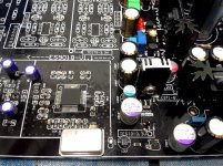
Some picture of reg and some playing with multiple bypassing at es9018.
Some question... do you guys also have *problem* with ams1117 1,2V regulator. It gets very hot. I installed heatsink on it but i can stil touch it for max 6-7 sek. Can somebody measure resistance between 1,2V output from regulator and GND on this dac? I measured about 0,6ohm.
Dac is working, lock led is turning on at output from es9018 i get signal...measured with scope, but output stage is not soldered because I look for another suggestion.
I do some modifications.....
Kubota regulator gets some ripple when you instal first 2sk246 ...i haven*t get 2sk30 that is on scheme. So i change it to bf245a biased to 1,8mA and ripple is much smaller.
Zener diode is changed to 3 LED, at output i put 600ohm 100khz inductor and ripple is almost 0.
3,3v ADP gets 1uf smd at input and output and also 600ohm ferrite after 220uf cerafine.
3,3v ams1117 is changed to lt1963 3,3v, ripple is 40% smaller and I can put os-con after reg. After ams1117 os-con is not a good choice.
Es9018 gets at VDD 100nF+10nF PPS+10UF smd
Avcc 1UF+10nF PPS
Dvcc 100nF+10nF PPS
I put original sheme parameters of second stage in
Multiple Feedback Low-pass Filter Design Tool
Cut-off frequency
fc = 95113.2706502[Hz]
Gain at f=0Hz
Gpk = -0.297872340426[times] (-10.5193964451)[dB]
Quality factor
Q = 1.00828259608
Damping ratio
ζ = 0.495892720894
Pole(s)
p = -47165.9785759 +82594.8225905i[Hz]
|p|= 95113.2706502[Hz]
p = -47165.9785759-82594.8225905i[Hz]
|p|= 95113.2706502[Hz]
Phase margin
pm= NAN[deg] (f =0[Hz])
Oscillation frequency
f = 82594.8225905[Hz]
Overshoot (in absolute value)
The 1st peak gpk = -0.35 (t =6.0E-6[sec])
The 2nd peak gpk = -0.29 (t =1.2E-5[sec])
The 3rd peak gpk = -0.3 (t =1.8E-5[sec])
Final value of the step response (on the condition that the system converged when t goes to infinity)
g(∞) = -0.297872340426
Why are all using so small resistor values and so large capacitor values. I don*t care of about 3db worse signal to noise ratio...but I think that with other values ...about 680-1000ohm stage will be on safer side...what do you think? I think that opamp with gain of 1 is more stable than with gain of 0.3. Am i wrong?
Some picture of reg and some playing with multiple bypassing at es9018.
Attachments

Hi,
I came across a DIY kit on ebay which uses Hi end ES9018 DAC chip.
ES9018 Hi End USB DAC 192K 32bit USB CM6631A Balanced Output Fiber Coax | eBay
ES9018 32bit 192kHz Hi End DAC Optical Coax and Balanced Output DIY Kit | eBay
An externally hosted image should be here but it was not working when we last tested it.
I need your view regarding similar kits.
Do they sound good?Close to similar high price DACs?
Anything to check before purchase?
Please guide me.
Thanks.
Similar DACs are now available in electronic stores near your place in Mumbai at cheap prices than these, check it out
Hello androa76.
Mine is 4 layer. No overheats the ams1117.
I asked to manufacturer DAC scheme to help solve my problem.
I mailed to manufacturer graphic measures before my answers on this forum.
But never responded me.
Do you have DAC scheme?
I have 6x AD797b original, but still have not SO8 SOIC8 SOP8 TO DIP8 adapter PCB converter. When they arrive, I will put new measures.
I am thinking I will remove the 7805 regulator.
I will solder three copper-foild in to TL1963 negative pin, to increase dissipation, and see if it works. It can be ease solution for this DAC.
Hello Oneclock,
Yes, according to schematic your dac feeds VDD 1,2 V from ic3 lt1963-3,3V. So you have voltage difference app. 2V and 110mA VDD consumption is then split in two 1117-1,2 regulators, so heat should be no problem.
My board is different. VDD reg. ams1117 1.2V becomes 5V at input and it is one for all VDD lines...so could be overheated. Can you please measure with multimeter resistance from GND to 1,2V output. So from left pin to center pin in 2 regs AMS1117 1,2V
According to schematic and binder i see that you also have the same problem but with first regulator. Middle LT1963 fedds 2 AMS117-1,2v and VDCC 3,3v.
Why do you have 14V at input? First thing...use 6V transformer and all will be fine.
If you don*t have it, instal 10ohm 3W resistor in front of that reg. LT1963 are low drop reg. 4V at their input wil work...but better is more than 5V. With 6V transformer you get app. 7-7,5V or even more which is fine, because 6V transformer always have some more voltage at secondaries.
After AMS1117-1,2v try to cut lines and instal 600ohm ferrite. Put 10uf smd on the top of 0,1uf smd. Ferrite + cap = noise filter.
I have done on all lines and noise is much smaller.
Interesting is that noise in VDD lines are dancing with the music...Try and you will se.
If bass is drumming or singer is singing...after loud transients...noise lines on scope are also going higher and lower....like old marantz vintage tuner scopes 🙂
I will investigate that further with other regulators...and other caps.
Some more things that i have learned from last es9018 dac.
22-47uf Vref cap near opamp. Use 1uf smd 1206 + 10nf 1206 pps ECHU under the board and on top 10uf tantal, smd 1206. Highs are less harsh and microdinamics and details are brilliant, excellent. Middle range....better saying 6khz-10khz ...for me, nasty harsh spekter is not so pronounced.
Try to use PPS or mkt ( red wima is little softer) or MKP on analog supply lines ...also in es9018 3,3V AVCC supply. Ceramics sounds thin...plastic, no emotions in music.
Opamps... I tried all sort in Minimax dac.
Ad797 is overheated at first i/v position also LMe49990 but sound was good.
At the end I have used lme79720 metallcan not plastic one on i/v and lme49990 on output putted into classA with Bf245.
Everyone have his own combination...depends on taste, system...
What do you think about output stage schematic???
Btw if you need schematic for your green dac, send me your mail. I have other problem, i can*t get schematic for my dac board 🙂
Attachments
Hi Oneclock,
It's really great that your sharing your improvements on the AVCC supply. If you want to get the most out of the AVCC supply I highly recommend the Dual Trident from TwistedPear. Just feed it 5-5.25VDC and its really easy to install.
I'm really interested in purchasing something to test with. What are you using?
Attachments

Why are all using so small resistor values and so large capacitor values. I don*t care of about 3db worse signal to noise ratio...but I think that with other values ...about 680-1000ohm stage will be on safer side...what do you think?
Which resistors are these? If they are in an opamp's feedback loop, I'd want them to be around 1K or so. Lower values will increase distortion and heat dissipation.
Hello Androa:
The two outputs AMS1117-1.2 V: 242 and 288 Oh. (5 mA).
The DAC comes with a 9 V + 9V transformer for digital sources.
One 9 V. provides 13.8 V at the input of LT1963 + 2x AMS1117.
Other 9 V. for the 7805 and LM317 + ADP150.
LT1963 digital cooler than analogs.
Now both analog LT1963 14.3 V. before, now 5V.
Hello Damuffin:
I have the finished the DAC. The sound is better than others DAC I have. The LT1963 regulators are very good. I have done measure at all points of the DAC and is running fine after correcting dissipation problem.
It is difficult to replace with trident without damaging DAC if there is no problem to solve.
Attachments
Hi Oneclock,
The problem with the Avcc supply is the uV ripple coming in. The 7805 as a pre-reg will help lower the ripple to the post-reg but for even better results add a large Silmic between.
You need to measure the uV ripple if you want to compare it with the Trident (Shunt regulator).
The problem with the Avcc supply is the uV ripple coming in. The 7805 as a pre-reg will help lower the ripple to the post-reg but for even better results add a large Silmic between.
You need to measure the uV ripple if you want to compare it with the Trident (Shunt regulator).
Hi Damuffin.
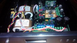
Behind the 7805 there is a 4700 uF electrolytic capacitor. It does not see good in the photo, it is black gold letters.
Talk you about 50 Hz AC ripple input or ripple with music output?
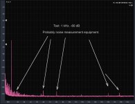
It´s about my graphs? DAC measures: the noise that appears on the graph is from my measure card (motu ultralite mk3) no from DAC.
I have pending a very low noise power supply with excellent 50 Hz. rejection for my measure card. Now is a simply external transformer to 12 v. cc.
I can measure both the AVCC DAC and Trident regulator in a Buffalo DAC. I compare next week.
Behind the 7805 there is a 4700 uF electrolytic capacitor. It does not see good in the photo, it is black gold letters.
Talk you about 50 Hz AC ripple input or ripple with music output?
It´s about my graphs? DAC measures: the noise that appears on the graph is from my measure card (motu ultralite mk3) no from DAC.
I have pending a very low noise power supply with excellent 50 Hz. rejection for my measure card. Now is a simply external transformer to 12 v. cc.
I can measure both the AVCC DAC and Trident regulator in a Buffalo DAC. I compare next week.
Last edited:
Oneclock...
Thank you for measurement DVCC.
Have you mesured your dac with original output stage? Pictures in posts before.
Can you do measurement and picture of square output, 1khz 0db.
And 1khz sine wave ...or what is p.p. max output voltage at 0db.
Thank you.
Thank you for measurement DVCC.
Have you mesured your dac with original output stage? Pictures in posts before.
Can you do measurement and picture of square output, 1khz 0db.
And 1khz sine wave ...or what is p.p. max output voltage at 0db.
Thank you.
thommy, did you get this sorted? Sounds very much like one of your op-amps has border-line stability, perhaps decoupling is not optimum on that board. Which op-amps are you using? May be worth trying something slower.
I shelved it along with my other projects for the rest of 2014. Am now close to being set up in a new workspace so am back on the forums & will be picking up the 2 layer 9018 board again sometime soon with a view to taking care of the noise issues I seemed to be having last year.
We live in the same county, so maybe you can cast an eye over the board for me at some point.
I built this DAC using a RaspBerry PI (type B) to control it, which works fine, but now I want to put it into an aluminium case. Problem with the PI is that the USB connector is connected to the (digital) ground. Should I connect it to the (grounded) chassis? Or would that cause ground loops or hum?
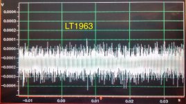
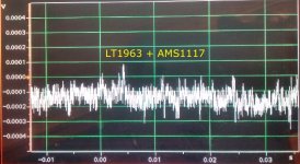
I measured LT1963 + AMS1117 and compared with Trident. I could not find differences.
The measures are to 1 kHz. 0 dB in analog output. Normally I measure with audio card 0 dB line input.
With maximum sensitivity oscilloscope impossible to see differences.
Measure is the same with audio card, microphone input, gain set to maximum +60 db. To ensure I put also Placid HD (+60 db amplified).
Attachments
Your mesurements on the audio output are not relevant to the regulator output. Voltage ripple is what is relevant. The chip will reduce-mute noise but the distortion from the ripple will be amplified durring playback.
Hello Damuffin:
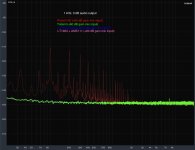
It is not measurements on the audio output. It is measure the ripple voltage in regulators outputs. It is the spectral measure of ripple with +60 dB amplification.
My oscilloscope has 2 mV. maximum sensitivity. 1 uV is -120 dBV. Ripple is measured at -145 dB in frecuency. It is 50 nV and is not visible. But I will measure ripple with a device with uV. sensivity. In time if for you no valid in frecuency.
Last edited:
Wow, that is a very surprising discovery. That is great news for anyone who owns this DAC. The AVCC in stock form was awful.
I have new measures with 0.1 mV resolution on another device. Show new information. Maybe not as good as supposed by calculations with the measured frequency. Also 50 nV. made no sense as LT1963 features: Low Noise 40μVRMS
Attachments

Last edited:
Hello Oneclock,
I have other problem, i can*t get schematic for my dac board 🙂
Hi, androa76, your schematics you will find here I've got it from the seller.
- Home
- Source & Line
- Digital Line Level
- DIY ES9018 Hi-end USB DAC